(1*,1((5,1*,1)250$7,21 ,QWHUQDWLRQDO(QJOLVK
MICROMASTER 420 Reference Manual
10 Issue A1
2.3
Positive Temperature Coefficient Resistor Use
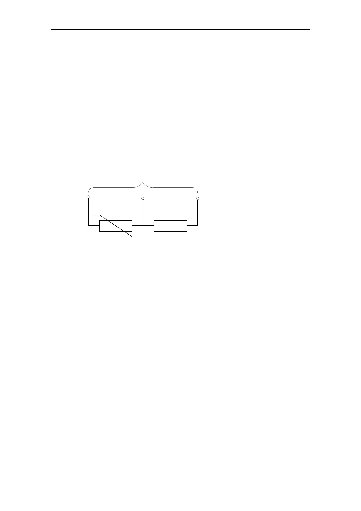
Many motors are available with a Positive Temperature Coefficient (PTC) resistor
built into the windings. The resistance of the resistor rises rapidly at a particular
temperature and this change can be detected by the inverter. If the resistor is
connected to the inverter terminals as shown in Figure 2-2, and the PTC input
enabled by setting parameter P087=001, then if the resistance rises above 2 kΩ,
the inverter will trip and Fault Code F004 displayed.
Most Motor Protection PTC resistors have a resistance of 2-300 ohms when cold
and this value rises rapidly at the ‘knee point’ to typically 10 kΩ and greater. The
PTC input is set so that it will operate at 1 kΩ minimum, 1.5 kΩ nominal, and 2 kΩ
maximum. The input has considerable filtering because the PTC connection
usually carries considerable Electro Magnetic Interference (EMI). On this basis two
or three PTCs may be connected in series when a motor has more than one PTC
built in, or if two or three motors are connected to the inverter output and require
individual protection.
Inverter Control Terminals
Motor PTC 1 KΩ
8 5, 6 or 7 9
Figure 2-2 PTC Resistor Connections
2.4 I
2
t Performance
When the motor is running at low speed and high load, the built-in cooling fan may
not provide enough cooling and the motor may overheat. Parameter P074 allows a
frequency dependent I
2
t limit to be enabled to protect the motor.
When the inverter is operating in the region above the selected curve (i.e. at low
frequency and high current), a timer is started, and after some time, (based on the
current, the motor size and previous operating history), the inverter will trip or
reduce output frequency. Trip or reduction of output frequency will depend on the
parameter setting.
2.5 Internal Overtemperature
Under normal circumstances, the inverter will not overheat. A heatsink and fan
combine to maintain the inverter at normal operating temperature. Careful
consideration when mounting the inverter will ensure adequate ventilation and
reduce the likelihood of overheating. Check to see whether other units may restrict
airflow.
The heatsink temperature is monitored using a PTC resistor and the inverter will
trip if the maximum temperature is exceeded. If the inverter persistently trips, you
should check for high ambient temperature, a faulty fan, or blocked airflow.
You can verify the heatsink temperature by displaying Parameter r0037. Units are
given in degrees Celsius (
o
C). Removing a faulty fan is described in Chapter 6,
Maintenance.

 Loading...


