(1*,1((5,1*,1)250$7,21 ,QWHUQDWLRQDO(QJOLVK
MICROMASTER 420 Reference Manual
20 Issue A1
2.9
Braking
Reducing the output frequency of the inverter will cause the motor to slow down
and as the frequency is gradually reduced to zero the motor will stop. Reducing
the output frequency too rapidly may cause the motor to act as a generator and
cause a negative current (regeneration) to return to the DC link. To overcome this
possibility the MICROMASTER 420 employs a number of methods to control
braking. These options are described in the following paragraphs.
The method of bringing the motor to a standstill is selected by the user depending
on operational requirements.
2.9.1 Normal Braking
The usual or normal braking method is to allow the motor to come to a standstill at
the selected ramp-down rate (OFF1), to coast to a standstill (OFF2) or to quickly
ramp down (OFF3) without applying any additional braking. (Refer to parameters
P0701, P0702 and P0703). However, if regeneration does cause tripping, DC or
Compound braking methods may be considered.
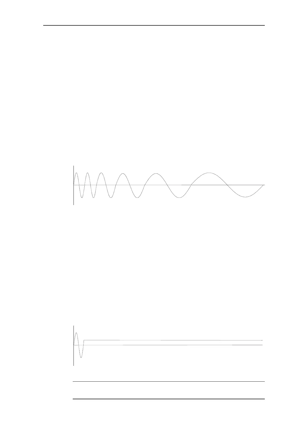
Figure 2-11 Frequency Ramp Down
2.9.2 DC Braking
In this method a controlled DC voltage is applied to the rotor. When using DC
braking, the inverter output pulses are disabled and the actual time taken to bring
the motor to a standstill cannot be predicted. Stored energy in the motor and the
load is dissipated in the rotor therefore no regeneration occurs.
The DC braking current is defined as a percentage of nominal motor current using
parameter P1236. The current will be applied only when the motor is sufficiently
demagnetized. If the demagnetization time for the motor (P0347), is reduced too
much then the drive will trip on over current (F0001) when DC braking is activated.
DC braking can be enabled by an external source such as a digital input.
Figure 2-12 DC Braking
1RWH
Frequent use of DC braking can cause the motor to overheat.

 Loading...


