,QWHUQDWLRQDO(QJOLVK &20081,&$7,216
MICROMASTER 420 Reference Manual
Issue A1
43
3.3
Using the Universal Serial Interface Protocol
The Universal Serial Interface Protocol (USS) protocol defines an access
technique according to the master-slave principle for communications via a serial
bus. One master and a maximum of 31 slaves can be connected to the bus. The
individual slaves are selected by the master via an address character in the
telegram. A slave itself can never transmit without first being requested to do so,
and direct message transfer between the individual slaves is not possible.
3.3.1 Telegram structure
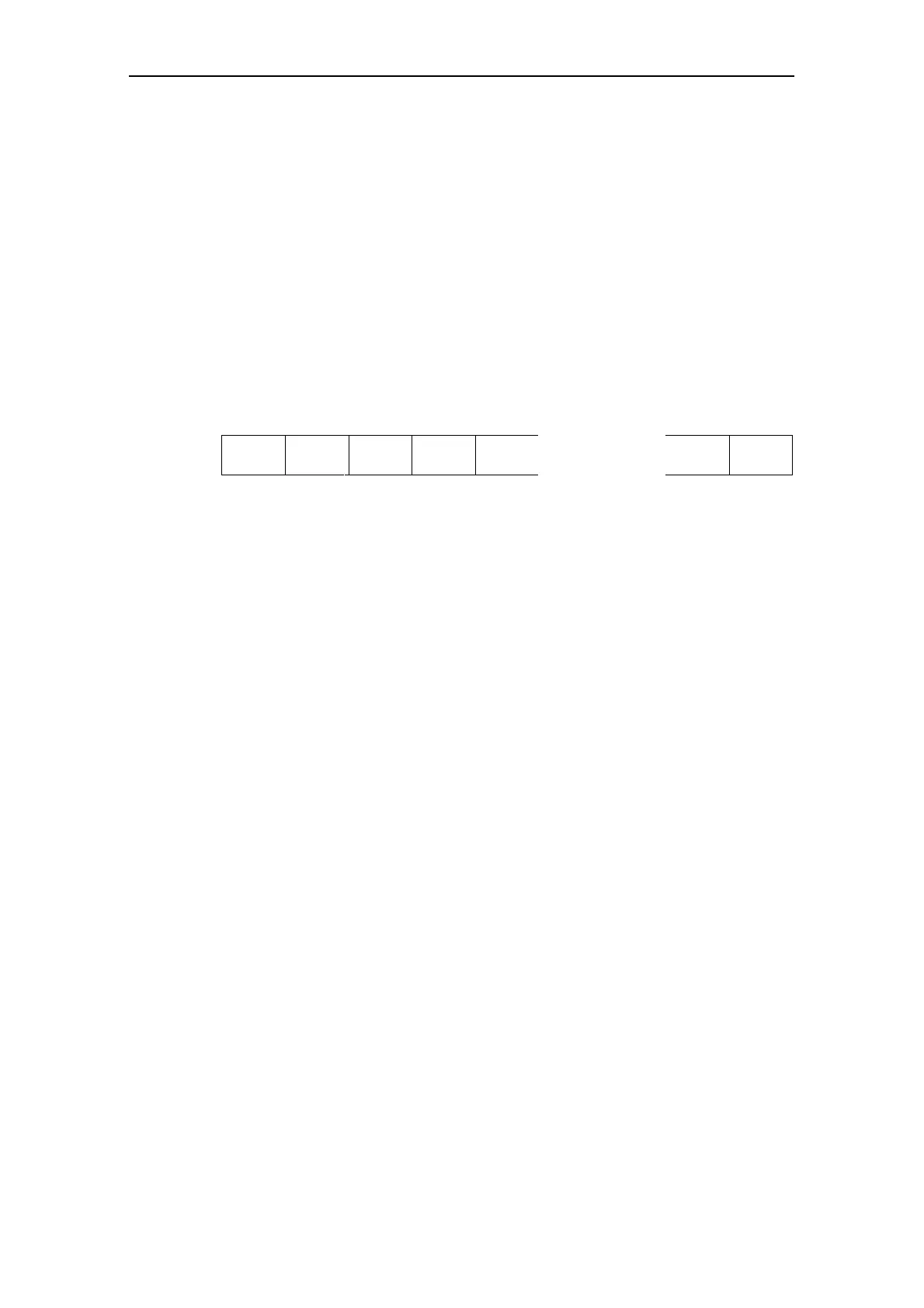
Each telegram starts with the STX character (= 02 hex), followed by the length
specification (LGE) and the address byte (ADR). The useful data characters then
follow. The telegram is terminated by the block check character (BCC).
STX LGE ADR 1 2 …….n BCC
|< ---- Useful data characters ---- >|
Figure 3-2 Telegram Structure
3.3.2 Detailed Description of the USS Protocol Message
67;
The STX field is a single byte ASCII STX character (02 hex) used to
indicate the start of a message.
/*(
The LGE is a single byte field indicating the number of bytes, which
follow this in the message. According to the USS specification, the
telegram length is variable, and the length must be specified in the 2
nd
telegram byte (i.e. LGE). Depending on the configuration, fixed
telegram lengths can be defined (see description of PKE and PZD
areas). Different telegram lengths can be used for different slave nodes
on the bus. The maximum total length of a telegram is 256 bytes. The
LGE is defined as the useful data characters (quantity n), address byte
(ADR) and the block check character (BCC). The actual total telegram
length will of course be two bytes longer than the LGE as the STX and
LGE bytes are not counted in the LGE.
For MICROMASTER 420 variable length telegrams and fixed length
telegrams can both be used. This can be selected using parameters
P2012 and P2013 to define the PZD and PKW lengths. Most common
fixed length applications will use a 4-word (8-byte) PKW area and a 2-
word (4-byte) PZD area giving 12 useful data characters.
This gives the LGE = 12 + 2 = 14
$'5
The ADR field is a single byte containing the address of the slave node
(e.g. inverter). The individual bits in the address byte are addressed as
shown in Figure 3-3.

 Loading...


