&20081,&$7,216 ,QWHUQDWLRQDO(QJOLVK
MICROMASTER 420 Reference Manual
44 Issue A1
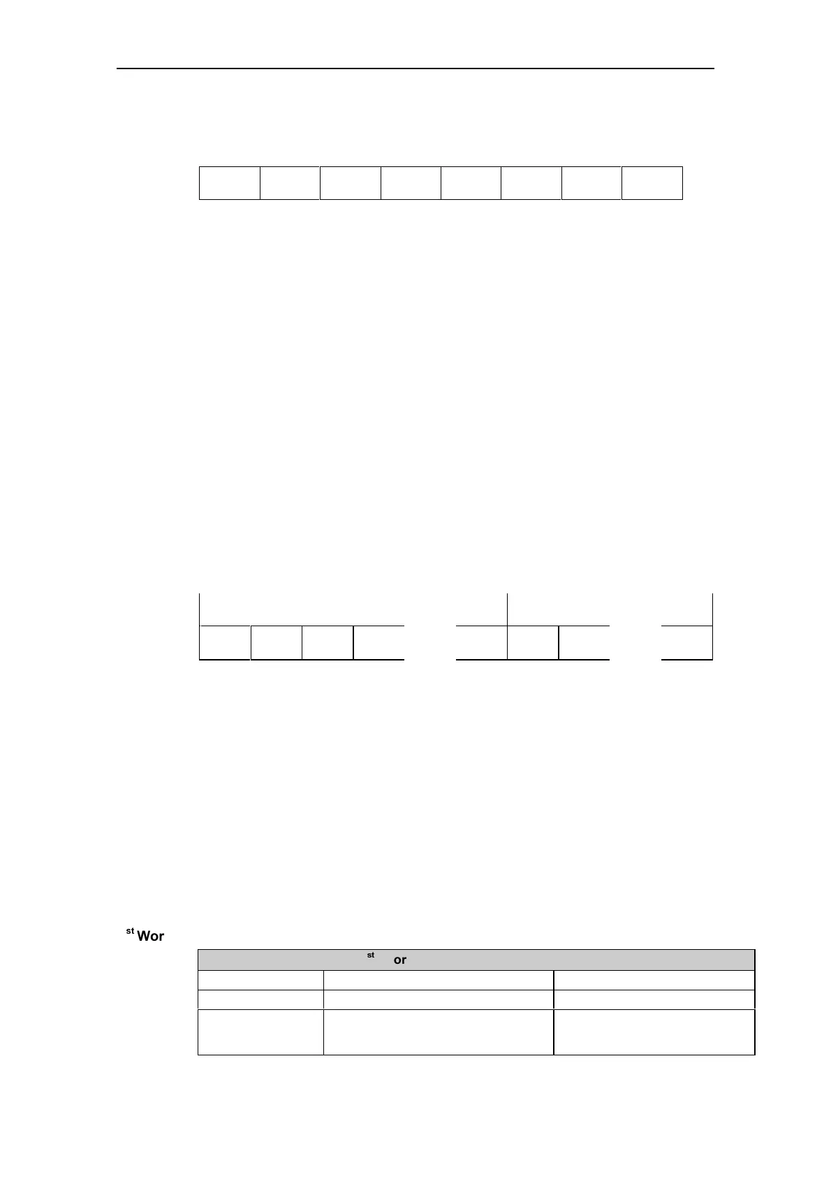
76543210
0XX
--- slave node addresses
0 - 31
--- >
Figure 3-3 Address (ADR) Bit Numbers
Bit 5 is the broadcast bit. If it is set to 1, the message is a broadcast message and
will be acted upon by all inverters on the serial link. The node number is not
evaluated. The USS protocol specification requires certain settings in the PKW
area. Refer to the later example on using USS broadcast mode.
Bit 6 indicates a mirror telegram. The node number is evaluated and the
addressed slave returns the telegram unchanged to the master.
The unused bits should be set to 0.
%&&
The BCC field is a byte-sized checksum used to validate messages. It
is calculated by XORing together all the previous bytes in the message.
If the Inverter receives a message with an invalid message it will discard
the message and not send a reply.
3.3.3 Useful Data Characters
The useful data block is divided into two areas, the PKW area (parameter ID –
value area) and the PZD area (process data).
|< --- PKW area --- >| |< --- PZD area --- >|
PKE IND PWE1 PWE2 …… PWEn PZD1 PZD2 ……. PZDn
Figure 3-4 Useful Data Characters
3.:DUHD3DUDPHWHU,'±YDOXHDUHD
The PKW area relates to the handling of the parameter ID - value (PKW) interface.
The PKW interface is not a physical interface but a mechanism which handles
parameter transfer between two communication partners (e.g. control unit and
inverter). This involves, for example, reading and writing parameter values.
6WUXFWXUHRI3.:DUHD
The first two words of the PKW area (PKE and IND) give information regarding the
task requested by the master (Task ID) or the type of reply telegram (Reply ID).
They also define the inverter parameter number (PNU) which is being accessed by
the telegram. The PNU number refers to MICROMASTER 420 parameter numbers
e.g. 1082 = P1082 = F
max.
VW
:RUG
VW
:RUG%LW 3.( 3DUDPHWHU,'
Bits15-12 AK = Task or reply ID. See below.
Bit 11 SPM = parameter change report. Not supported (always 0).
Bits10-00 b. PNU = basis parameter number. The complete PNU will be built
together with Bits 15-12 from the IND
(index). See below.

 Loading...


