EasyManuals Logo

Siemens MICROMASTER 420 Reference Manual

Siemens MICROMASTER 420
94 pages
To Next Page IconTo Next Page
To Previous Page IconTo Previous Page
Page #76 background imageLoading...
Page #76 background image
237,216 ,QWHUQDWLRQDO(QJOLVK
MICROMASTER 420 Reference Manual
68 Issue A1
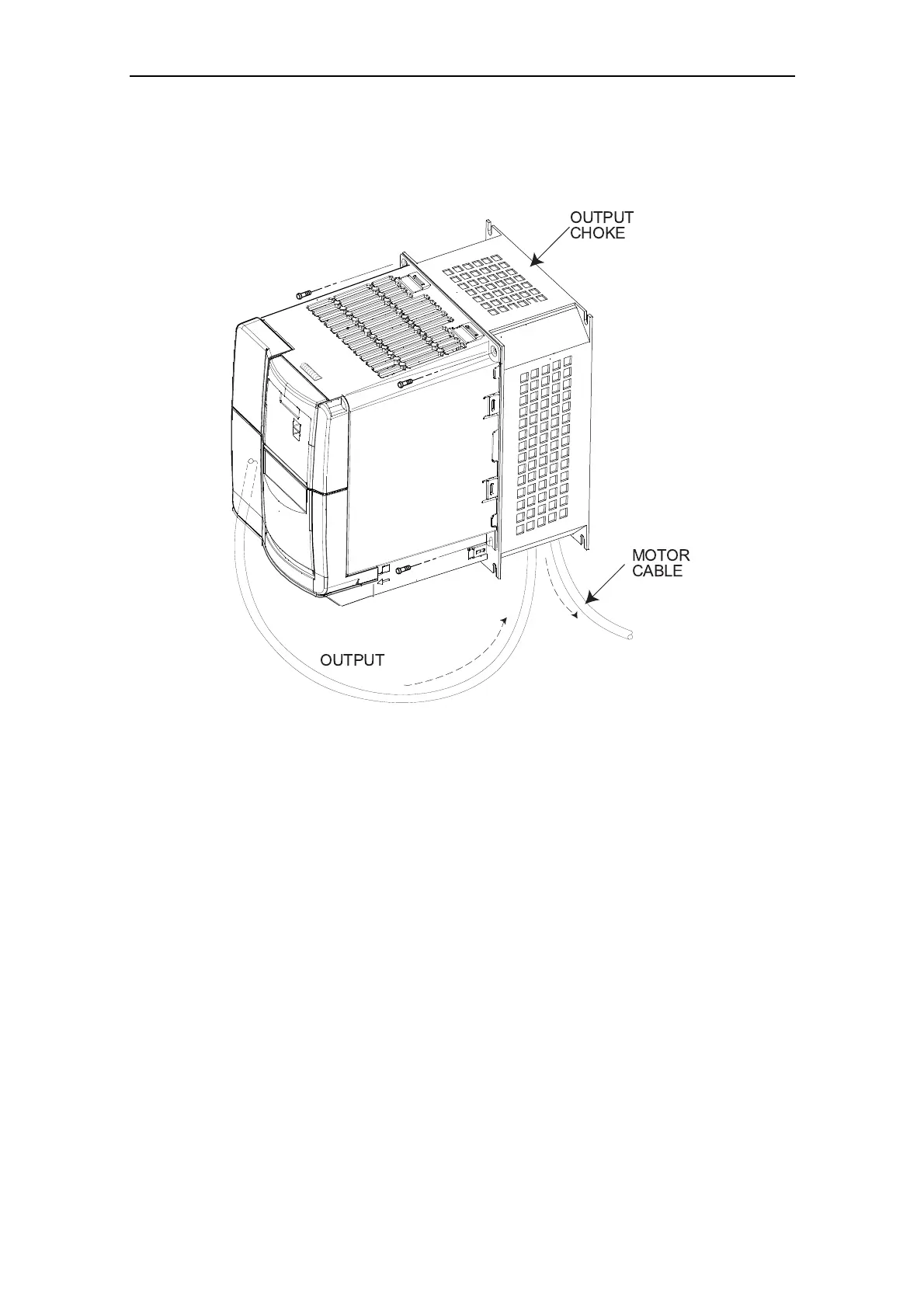
Figure 4-3 Inverter with Output Choke
4.2.3 Gland Plates
Gland plates are mechanical assemblies added to the inverters to assist the
installation of screened power and control cables. Shielded connections of the
power and control cables ensure optimum EMC performance. Please refer to the
CD-ROM supplied with the inverter for detailed installation drawings.
OUTPUT
CHOKE
MOTOR
CABLE
OUTPUT

Table of Contents

Other manuals for Siemens MICROMASTER 420

Questions and Answers:

Question and Answer IconNeed help?

Do you have a question about the Siemens MICROMASTER 420 and is the answer not in the manual?

Siemens MICROMASTER 420 Specifications

General IconGeneral
Power Range0.12 kW to 11 kW
Output Voltage0 to input voltage
Input Frequency47 Hz to 63 Hz
Output Frequency0 Hz to 650 Hz
Overload Capacity150% for 60 seconds
Enclosure RatingIP20
Input Voltage200 V to 240 V (±10%), 380 V to 480 V (±10%)
Control TypeV/f control
BrakingOptional braking module
Protection FeaturesOvercurrent, overvoltage, undervoltage, overload, short circuit, ground fault
CoolingAir-cooled
Ambient Temperature-10 °C to +50 °C
Communication InterfacesUSS protocol

Related product manuals