,QWHUQDWLRQDO(QJOLVK (1*,1((5,1*,1)250$7,21
MICROMASTER 420 Reference Manual
Issue A1
35
2.17
Acoustic Noise
Laboratory tests have determined the level of noise generated by the range of
MICROMASTER 420 Inverters.
7HVW&RQGLWLRQV
1 The inverters were set up to run a standard 4-pole Siemens motor at
frequencies from 0 – 100 Hz.
2 All specified switching frequencies were tested with loads of 25%, 50%,
75% and 100%.
3 The sound level recorder was set up 1 metre from the inverter being tested.
4 The motor was situated outside the noise area and the meter then set to
record the levels of noise at three areas around the inverter:
a. At the front of the inverter
b. At the rear of the inverter
c. At the right hand side of the inverter
The sound levels were measured with the inverter running and stopped, i.e. with
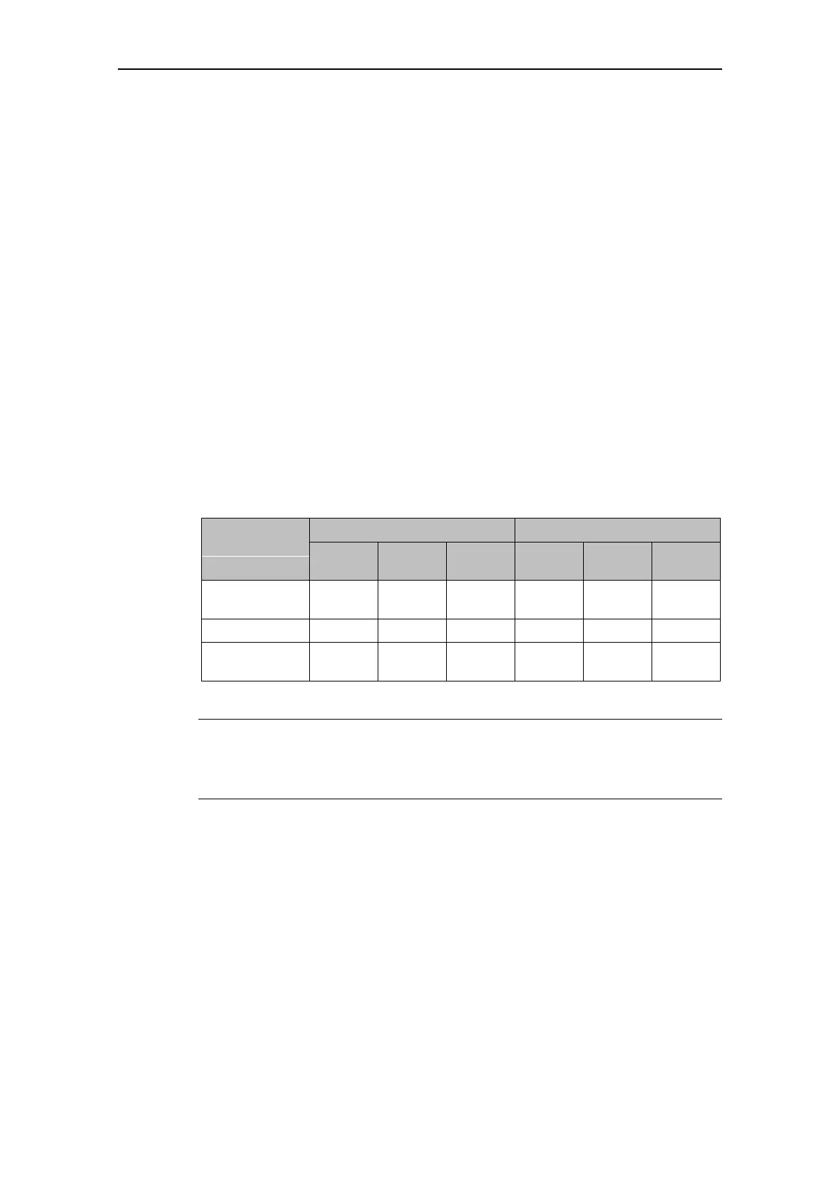
the fan on and off. Table 2-11 shows the average results, (in decibels).
Table 2-11 Acoustic Test Results
)DQ5XQQLQJ )DQQRWUXQQLQJ$UHDRILQYHUWHU
WHVWHG
,QYHUWHU$
G%
,QYHUWHU%
G%
,QYHUWHU&
G%
,QYHUWHU$
G%
,QYHUWHU%
G%
,QYHUWHU&
G%
Front of inverter
(BOP area)
52.0 54.0 61.0 51.0 50.0 50.0
Rear of inverter 52.0 55.0 64.0 51.0 51.0 50.0
Right hand side
of inverter
60.0 59.0 70.0 52.0 51.0 51.0
1RWH
Inverter A: MICROMASTER 420 FSA 230 V 750 W 1-ph filtered
Inverter B: MICROMASTER 420 FSB 230 V 2.2 kW 1-ph filtered
Inverter C: MICROMASTER 420 FSC 230 V 5.5 kW 3-ph filtered

 Loading...


