7528%/(6+227,1* ,QWHUQDWLRQDO(QJOLVK
MICROMASTER 420 Reference Manual
76 Issue A1
:DUQLQJV
• Repairs on equipment may only be carried out by 6LHPHQV6HUYLFH, by
repair centers DXWKRUL]HGE\6LHPHQV or by qualified personnel who
are thoroughly acquainted with all the warnings and operating
procedures contained in this manual.
• Any defective parts or components must be replaced using parts
contained in the relevant spare parts list.
• Disconnect the power supply before opening the equipment for access.
5.1
Troubleshooting with Status Display Panel
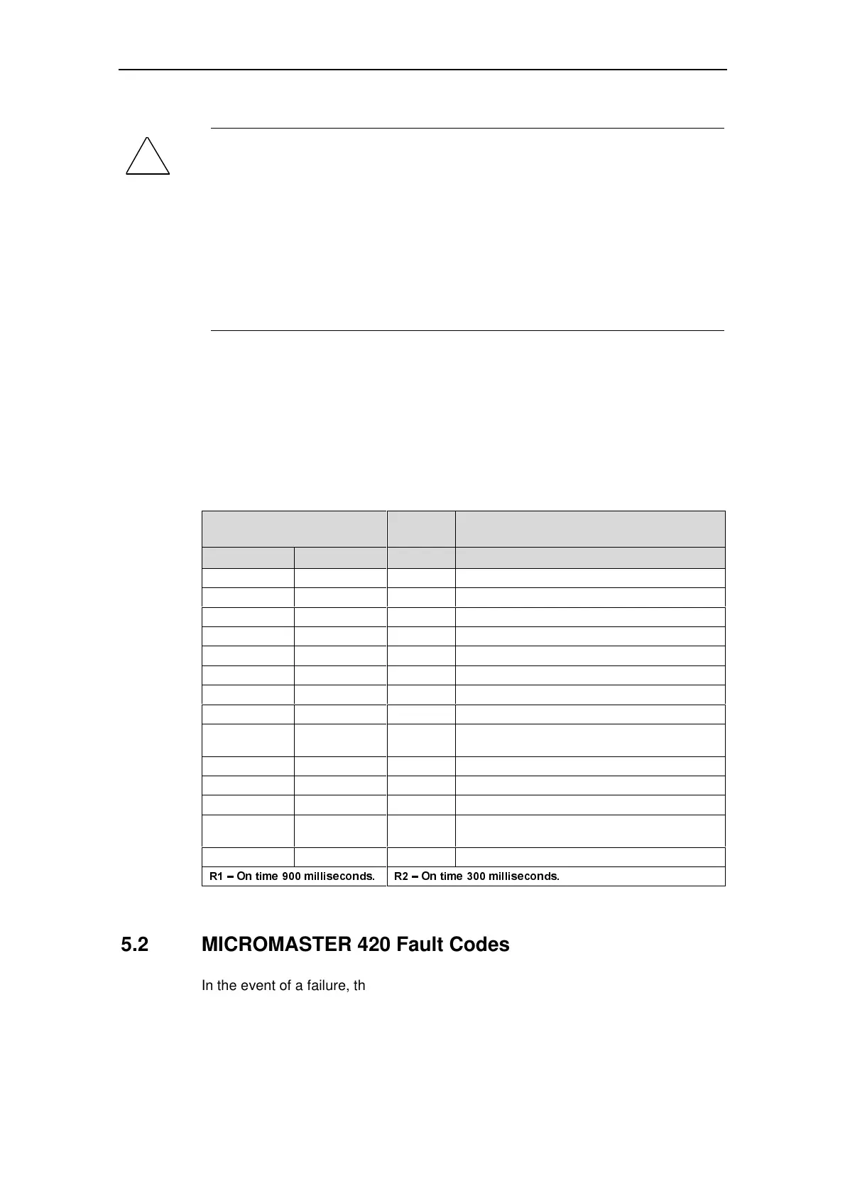
Table 5-1 explains the meaning of the various states of the LEDs on the Status
Display Panel (SDP).
Table 5-1 Inverter conditions indicated by the LEDs on the SDP
/('V
3ULRULW\
'LVSOD\
,QYHUWHU6WDWXV'HILQLWLRQV
*UHHQ <HOORZ
OFF OFF 1 Mains not present.
OFF ON 8 Inverter fault – other than those listed below.
ON OFF 13 Inverter running.
ON ON 14 Ready to run – standby.
OFF Flashing – R1 4 Fault – Overcurrent.
Flashing – R1 OFF 5 Fault – Overvoltage.
Flashing – R1 ON 7 Fault – Motor Overtemperature.
ON Flashing – R1 8 Fault – Inverter Overtemperature.
Flashing – R1 Flashing – R1 9
Warning Current Limit (both LEDs flashing at the
same time).
Flashing – R1 Flashing – R1 11 Other warning (both LEDs alternate flashing).
Flashing – R1 Flashing – R2 6/10 Undervoltage trip/Undervoltage warning.
Flashing – R2 Flashing – R1 12 Inverter is not in ready state – display >0.
Flashing – R2 Flashing – R2 2
ROM failure (both LEDs flashing at the same
time).
Flashing – R2 Flashing – R2 3 RAM failure (both LEDs alternate flashing).
5±2QWLPHPLOOLVHFRQGV 5±2QWLPHPLOOLVHFRQGV
5.2 MICROMASTER 420 Fault Codes
In the event of a failure, the inverter switches off and a fault code appears on the
display. See Operating Instructions, Chapter 6, Troubleshooting for an explanation
of these codes.

 Loading...


