5. SYSTEM PARAMETERS International English
MICROMASTER 420 Operating Instructions 89
6SE6400-5AA00-0BP0
Parameter
Number
Parameter Name
Min
Max
[Default]
Units
♦
♦♦
♦P0003 User
Access Level
♦
♦♦
♦P0004 Setting
♦
♦♦
♦Changeable
♦
♦♦
♦Status
P2271 PI: tranducer type
Allows the User to select the PI feedback signal Transducer type.
0: = [default] if the feedback signal is less than the PI setpoint the PI controller will
increase motor speed to correct this
1: = if the feedback signal is less than the PI setpoint the PI controller will reduce motor
speed to correct this
Note
It is very important that the transducer type is correctly selected. If you are unsure that it
should be either 0 or 1 you can determine the actual type as follows:
Disable the PI function (P2200 = 0). Increase the motor frequency while measuring the
feedback signal. If the feedback signal increases with an increase in motor frequency the
transducer type should be 0.
If the signal decreases with an increase in motor frequency the transducer type should be
set to 1.
0
1
[0]
-
2
22
‘•’
CO: PI scaled feedback signalr2272
-
-
[-]
%
2
22
CO: PI errorr2273
Displays the PI error (difference) signal between the setpoint and feedback signals in
percent.
-
-
[-]
%
2
22
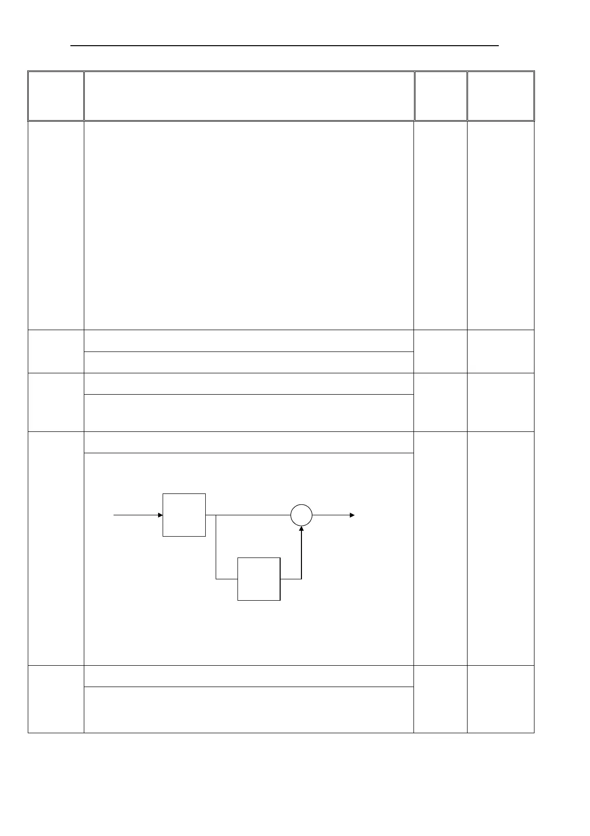
PI: proportional gainP2280
Allows the User to set the proportional gain of the PI controller.
The PI controller on MM420 is implemented using the standard model:
I
P
output
error
+
+
Best results are usually obtained if both P and I terms are enabled. If the system is liable
to sudden step changes in feedback signal, the P term should usually be set to a small
value (L 0.5) with a faster I term for optimum performance.
If the P term is set to 0 the I term acts on the square of the error signal.
0
125
[3]
-
2
22
‘•’
PI: integral timeP2285
Allows the User to set the PI controller integral time constant.
Refer to P2280 above for detail.
0
100
[0]
s
2
22
‘•’

 Loading...


