International English 3. COMMISSIONING
30 MICROMASTER 420 Operating Instructions
6SE6400-5AA00-0BP0
DIN1
5
DIN2
6
DIN3
7
24V+
8
0V
9
10V+
1
0V
2
AIN+
3
AIN-
4
Start/Stop
Rev
Ack
5.0 k
W
Digital Inputs Analogue Inputs
Warnings and faults states on the Status Display Panel
The two LEDs on the Status Display Panel indicate the operating status of your inverter.
These LEDs also indicate various warnings or fault states. In section 6.1 the inverter
states, indicated by the two LEDs are explained.
3.1.2 Basic operation with SDP
With the SDP fitted, the following is possible:
♦ Start and stopping the motor
♦ Reversing the motor
♦ Fault Reset
Controlling the speed of the motor
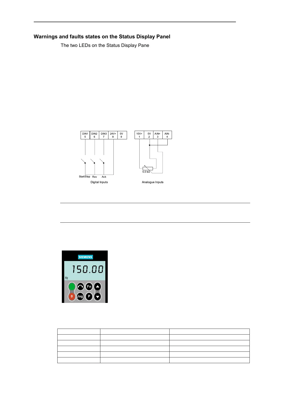
Connect the terminals as shown in the figure below.
Figure 3-2 Basic operation with SDP
Note
The terminal layout for connecting power and control cables is shown in the photographs
on the inside of the back cover of this manual.
3.1.3 Commissioning with the Basic Operator Panel (BOP)
The Basic Operator Panel (BOP), which is available as an
option, provides access to the inverter parameters and enables
you to customize the settings of your MICROMASTER 420. The
BOP can be used to configure several MICROMASTER 420
Inverters. There is no need to purchase a separate BOP for each
inverter.
It should be noted that the BOP motor control functions are
disabled by default. To control the motor via the BOP, parameter
P0700 should be set to 1.
Table 3-2 shows the factory default settings for operation via the
Basic Operator Panel.
Table 3-2 Default settings for operation using the BOP
Parameter Meaning Default Europe (North America)
P0100 Operating Mode Europe/US 50 Hz, kW (60Hz, hp)
P0307 Power (rated motor) kW (Hp)
P0310 Motor frequency rating 50 Hz (60 Hz)
P0311 Motor speed rating 1395 (1680) rpm [depending on variant]
P1082 Maximum Motor Frequency 50 Hz (60 Hz)
Jog
0
1
P
Fn
Hz
150.00

 Loading...


