Page 4 MFA 4p - INSTRUCTION MANUAL 7ML19985FM01
mmmmm
Installation
Installation
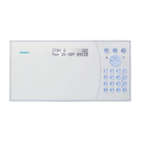
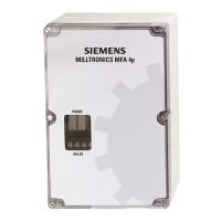
Milltronics MFA 4p
The MFA 4p (and RMA if applicable) must be mounted in a non-hazardous area that is
clean, dry, vibration-free, within the ambient temperature range, and non-corrosive to the
electronics or its enclosure. The door should be accessible for viewing and to allow
calibration of the MFA 4p.
Probe
The probe should be mounted onto a vibration free structure using the mounting flange.
The gap between probe and target should be large enough to prevent the target from
damaging the probe. The probe environment must be within the probe's ambient
temperature range and non-corrosive to the probe's body. Refer to Applications drawings
on page 23.
The probe design detects a changing magnetic field, typically caused by a ferromagnetic
target disturbing the probe's magnetic field. Extremely strong magnetic fields (like those
produced by the 30A/m requirements of 1EC 60004-8, Power Frequency Magnetic Field
Immunity test) will be detected and will result in loss of functionality.
Functionality loss indicators:
• alarm conditions by relay trip
• false pulse readings in LED1
Consider the probe location carefully before installation. Avoid strong magnetic fields
(50/60 Hz) from nearby power transformers, heater elements, or large industrial motors,
because these can affect the probe’s performance.
Wiring
Where possible, the probe components should be interconnected via flexible conduit.
This allows for easier removal or adjustment of the probe and mounting flange assembly.
Note: Do not mount MFA 4p in direct sunlight.
Note: Installation shall only be performed by qualified personnel and in accordance
with local governing regulations.
7ML19985FM01.book Page 4 Wednesday, May 21, 2008 2:17 PM
 Loading...