Connecting up, switching on
4.4 Installation set for line-side cable connection, left
Power Module PM330
Hardware Installation Manual, 12/2018, A5E32844552B AF
43
Installation set for line-side cable connection, left
Description
Alternatively, for devices, frame sizes GX and HX, the line connection can be established
using the "Installation kit for line-side cable connection, left".
This means that it is possible to mount the Power Module at the top of the control cabinet
without any clearance. This way it is possible to dissipate the power loss from the Power
Module from the cabinet with low design overhead.
For devices, frame size JX, the line feeder cables can only be connected from the top.
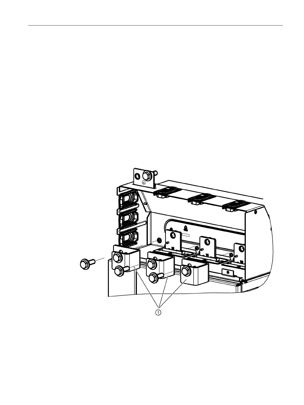
Installing the "Mounting kit for line-side cable connection, left" 6SL3366-1LG00-0PA0 for frame size
GX
The mounting kit is installed in 4 steps:
1. Remove the busbar adapter for the cable outlet towards the top
①.
Use the 7 screws (incl. PE) again for mounting the installation set.
Figure 4-5 Installing the mounting kit, step 1