Connecting up, switching on
4.6 Terminal block X41 / switch S41
Power Module PM330
Hardware Installation Manual, 12/2018, A5E32844552B AF
51
Terminal block X41 / switch S41
PM330 Power Modules, from function release (FS) 04 (see type plate), are equipped with
the safety subfunction Safe Torque Off.
This safety subfunction is controlled via terminal block X41 using digital inputs STO_A
(X41:1/2) and STO_B (X41:3/4).
Diagnostics of this safety subfunction can also be realized via terminal block X41 using the
two feedback signal contacts FB_A (X41:5/6) and FB_B (X41:7/8).
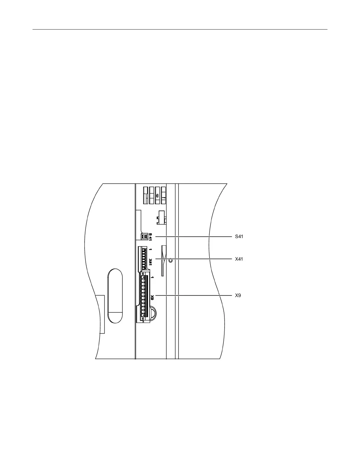
The two S41 switches are used to enable the STO function.
The power supply to control the STO inputs - as well as to diagnose the safety function
(feedback signal contacts) - should be located in the direct vicinity of the inverter (e.g. in the
same cabinet). The cable length to terminal block X41 must not exceed 30 m.
This safety subfunction is exclusively implemented in the hardware; as a consequence it is
not described in the Safety Integrated Function Manual, and a description is provided in this
document in Chapter "Fundamental safety technology principles (Page 105)".
Figure 4-13 Position of S41, X41 and X9 - side view after opening the left-hand housing flap