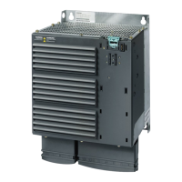
Power Module PM330
Hardware Installation Manual, 12/2018, A5E32844552B AF
3
1 Basic safety instructions .......................................................................................................................... 7
1.1 General safety instructions ....................................................................................................... 7
1.2 Handling electrostatic sensitive devices (ESD) ...................................................................... 11
1.3 Industrial security .................................................................................................................... 12
1.4 Residual risks of power drive systems .................................................................................... 14
2 Introduction ........................................................................................................................................... 15
3 Installing/Mounting ................................................................................................................................ 19
3.1 Installation conditions.............................................................................................................. 19
3.2 Power losses and air cooling requirements ............................................................................ 21
3.3 Mounting the Power Modules ................................................................................................. 23
3.3.1 Chassis units ........................................................................................................................... 26
3.4 Control Unit installation ........................................................................................................... 29
4 Connecting up, switching on .................................................................................................................. 31
4.1 Cable lugs ............................................................................................................................... 32
4.2 Line, motor and DC link connection ........................................................................................ 33
4.2.1 Protective conductor ............................................................................................................... 33
4.2.2 Line connection ....................................................................................................................... 34
4.2.3 Length of motor cables ........................................................................................................... 34
4.2.4 Motor connection .................................................................................................................... 35
4.2.5 Access to power and motor terminals ..................................................................................... 36
4.2.6 DC link connection .................................................................................................................. 40
4.3 Operation on a non-grounded line supply (IT system) ........................................................... 41
4.4 Installation set for line-side cable connection, left .................................................................. 43
4.5 Terminal strip X9 ..................................................................................................................... 49
4.6 Terminal block X41 / switch S41 ............................................................................................. 51
4.6.1 Terminal strip X41 ................................................................................................................... 52
4.6.2 Switch S41 .............................................................................................................................. 53
4.6.3 Schematic diagram of the safety relay at X41 ........................................................................ 54
4.7 EMC compliant connection ..................................................................................................... 55
4.7.1 Avoiding electromagnetic interference .................................................................................... 55
4.7.2 EMC-compliant cabinet design ............................................................................................... 55
4.7.3 Cabinet design ........................................................................................................................ 56
4.7.4 Cabling .................................................................................................................................... 57
4.7.5 Equipotential bonding ............................................................................................................. 59
4.8 Switching on ............................................................................................................................ 62
 Loading...


