Connecting up, switching on
4.6 Terminal block X41 / switch S41
Power Module PM330
52 Hardware Installation Manual, 12/2018, A5E32844552B AF
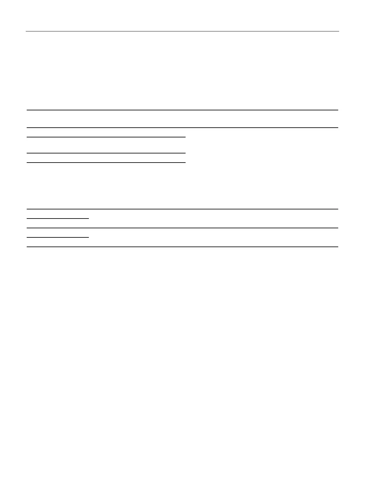
Terminal strip X41
Terminal strip X41
Table 4- 4 Terminal strip X41
Voltage: -3 V ... +30 V
Signal level (including ripple):
• High signal level: 15 V ... 30 V -> STO deselected (op-
eration possible)
• Low signal level: -3 V ... +5 V -> STO active (operation
inhibited)
Current consumption:
2 mA at <15 V
15 mA at 30 V
2 STO_AM Reference ground for
Reference
4 STO_BM Reference ground for
input STO_B1
Reference
Feedback signal contact
diagnostics channel A
Floating
contact
Voltage: -3 V ... +30 V
Max. current for a resistive load: 500 mA
Feedback signal contact
diagnostics channel B
Floating
contact
Voltage: -3 V ... +30 V
Max. current for a resistive load: 500 mA
Maximum connection cross section: 1.5 mm²
Minimum connection cross section: 0.2 mm²
Maximum tightening torque: 0.22 Nm (1.9 lbf in)
Control cable capacitance
Maximum control cable capacitance: 330 pF/m
Insulated end sleeves according to DIN 46228-4 must be used.
For strain relief, the cables to the Control Unit and to the terminal X41 must be fastened to
the lugs in the cable duct below terminal X9 (e.g. with cable ties).
If the cables are introduced at the side (at the height of terminal X9), the strain relief must be
provided outside the Power Module.