Appendix
A.4 Acceptance test/configuration test
Power Module PM330
Hardware Installation Manual, 12/2018, A5E32844552B AF
137
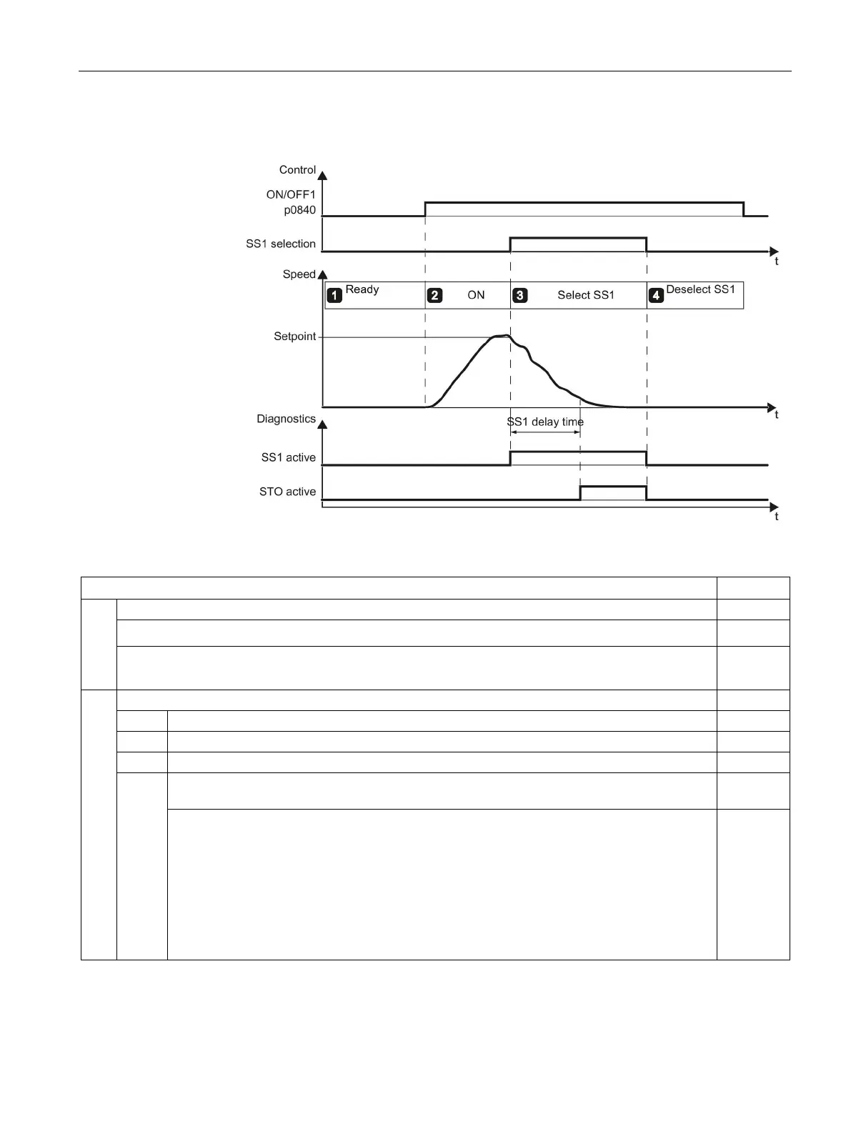
Table A- 5 Procedure for the SS1-t acceptance test
1.
The inverter is ready for operation
• The inverter signals neither faults nor alarms.
• STO is not active (r0002 ≠ 44).
(e.g. R0002 = [31] Ready for switching on – set "ON/OFF1" = "1/0" (p0840)
2.
2.1. Enter a speed setpoint ≠ 0.
Switch on the motor (ON command).
Check that the correct motor is running.
2.4. Check the status of the safety relay LEDs
(here in the example, a 3SK1112-… or 3SK112x-…)
• LED (1) DEVICE = green
• LED (2) OUT = green-> 3SK1 output circuit closed
• LED (3) IN = green-> 3SK1 switch-on (close) conditions satisfied
– Input circuit closed
– Feedback circuit closed
– Start button where necessary actuated
• LED (4) SF = OFF
 Loading...