Technical specifications
6.2 Specific technical data
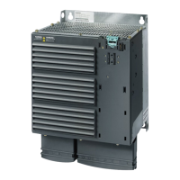
Power Module PM330
Hardware Installation Manual, 12/2018, A5E32844552B AF
91
Tightening torque for line, motor, DC link, and
50 Nm / 443 lbf in 50 Nm / 443 lbf in 50 Nm / 443 lbf in
Dimensions: Width x height x depth [mm]
Minimum control cabinet size for installation of the
Power Module (width x height x depth)
800 mm x 2000 mm x 600 mm
The line supply must be capable of supplying the minimum short-circuit current so that the fuses trigger and consequen-
tial damage is avoided.
Note: If the minimum short-circuit current is not reached, then the tripping time for the fuses increases, and this may re-
sult in consequential damage.
When semiconductor fuses are used, they must be mounted in the same higher construction as the inverter.
3)
When connecting a Braking Module with rated power 50 kW, P
20
power 200 kW.
 Loading...