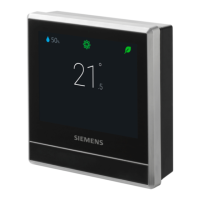
6/50 2015-02-27 CE1G2205xx
Mounting notes REV24..
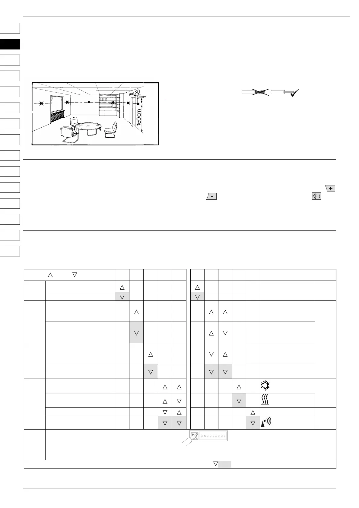
1 Placement of unit
· The REV24.. should be mounted in the main living room (for wall
mounting, refer to Figs. B through E)
· The REV24.. must be located such that it can acquire the room
temperature as accurately as possible, without getting affected by
direct solar radiation or other heat or refrigeration sources
min.
10 cm
2261Z03
2 Mounting
· Refer to Figs. A through E
3 Checking the wiring
For electrical connections, refer to “Connection diagram”.
Note: Do not use stranded wires, only solid wires
or stranded wires with ferrules!
4 Notes
· The local regulations for electrical installations must be complied
with
· If the reference room is equipped with thermostatic radiator
valves, they must be set to their fully open position
· External preliminary protection with max. C 10 A circuit breaker is
required in all cases
Commissioning
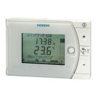
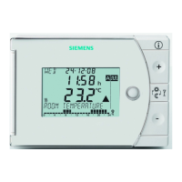
1 Switching on the REV24..
· Remove the black battery transit tab (Fig. F); as soon as the tab is
removed, the unit is ready to operate
(also refer to operating instructions)
2 Selecting the language
· When starting up, the display shows the type of controller at top left
and “THANK YOU …“ in all available languages on the text line
· Press one of the buttons to stop the running display. The choice
of languages starts with “ENGLISH“ (factory setting). Press
or until the language you require appears. Press or
move the slider to confirm the selected language (also refer to
Fig. G)
Configuration and function check REV24..
1 Configuration
1.1 DIP switches
ON / OFF 1 2 3 4 5 6 7 8 9 10
See
See
1.1.1
Sensor calibration on Periodic pump run on
1.1.5
Sensor calibration off Periodic pump run off
1.1.2
Setpoint limitation
16…35 °C
Optimum start
control:
1 h/°C
1.1.6
Setpoint limitation
3…35 °C
Optimum start
control:
¼ h/°C
1.1.3
Temperature display °F
Optimum start
control:
½ h/°C
Temperature display °C
Optimum start
control: Off
1.1.4
PID self-learning
(Cooling on)
1.1.7
PID 6
(Heating on)
PID12 Quartz
1.1.8
2-Point
Radio clock
1.1.9
DIP switch reset
ON
1 342
567 89
When changing one or several DIP switch positions, a DIP switch reset must be made by pressing the DIP switch reset button
(also refer to Fig. 8). Otherwise, the previous settings will be maintained!
1.1.9
Factory setting: All DIP switches OFF
DE
EN
FR
IT
NL
ES
PT
CS
HU
PL
SV
FI
DA
TR
EL
 Loading...