Connecting
4.2 Wiring of the push-pull connection block
RF180C communication module
24 Operating Instructions, 12/2012, J31069-D0177-U001-A6-7618
Wiring of push-pull connectors
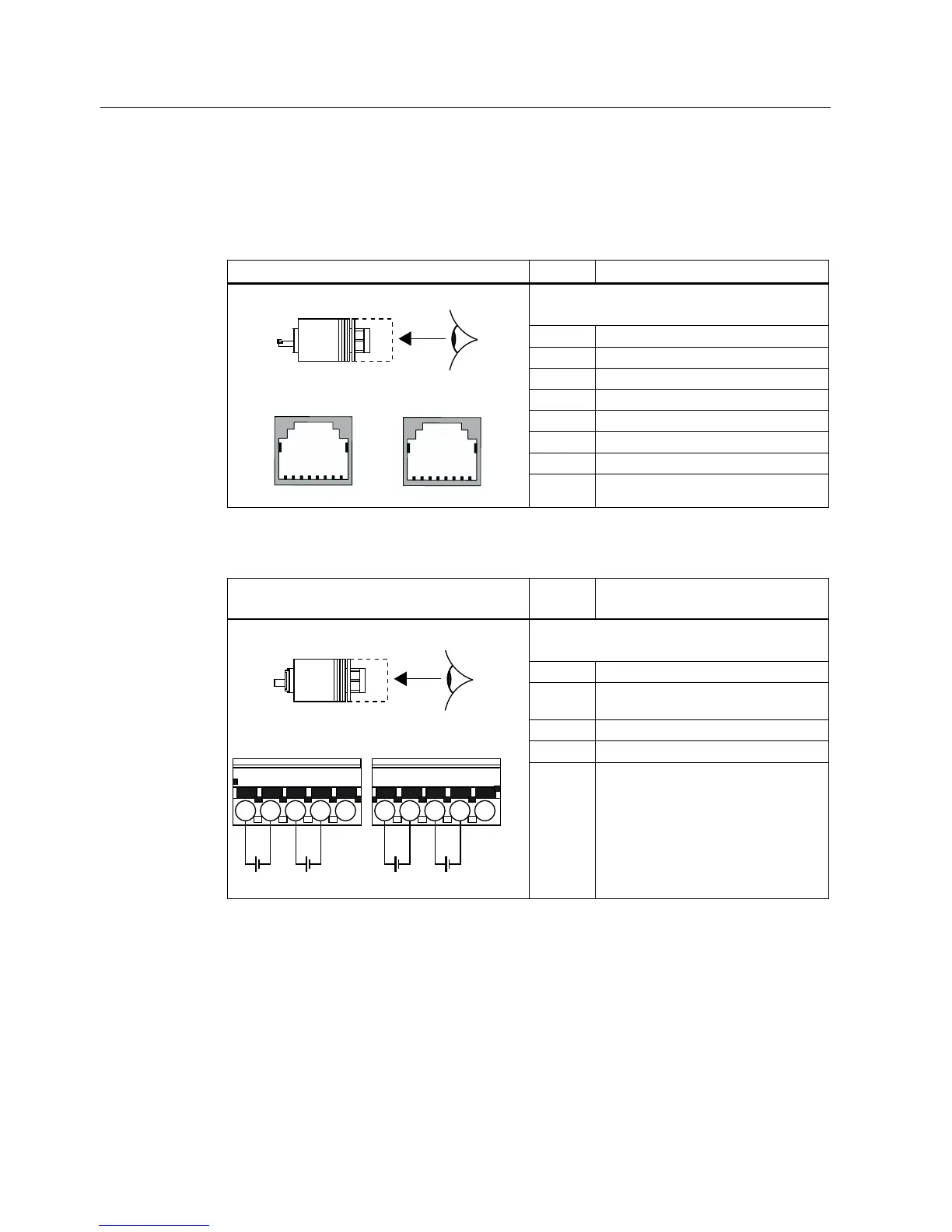
The tables below contain the pin assignment for the push-pull connectors:
Table 4- 3 Pin assignment of push-pull cable connectors (RJ-45)
View of push-pull cable connectors (RJ-45) Terminal Assignment
X03 PN1 for feeding of PROFINET
X04 PN2 for looping through of PROFINET
1 Receive Data+ RD
2 Receive Data- RD_N
3 Transmit Data+ TD
4 Ground GND (RJ-45)
5 Ground GND (RJ-45)
6 Transmit Data- TD_N
7 Ground GND (RJ-45)
;
31
;
31
8 Ground GND (RJ-45)
Table 4- 4 Pin assignment of push-pull cable connectors (1L+ and 2L+ supply voltages)
View of push-pull cable connectors (1L+ and 2L+
supply voltages)
Terminal Assignment
X01 DC 24 V for infeed
X02 24 VDC for looping through
1 Electronic/encoder supply 1L+ground
2 Ground for electronic/encoder supply
1M
3 2L+ load voltage supply
4 Ground for load voltage supply 2M
/ / / /
;
'&9
;
'&9
5 Functional ground (PE)