Connecting
4.2 Wiring of the push-pull connection block
RF180C communication module
Operating Instructions, 12/2012, J31069-D0177-U001-A6-7618
25
Note
When connecting the power supply, we recommend the cable specified in the section
"Ordering data (Page 63)" (cable 5 x 1.5 mm
2
pre-assembled with push-pull connectors).
If you want to assemble the cable yourself, then the conductor cross-section should be
1.5 mm
2
.
A cable cross-section of 2.5 mm² is mandatory for an amperage > 8 A.
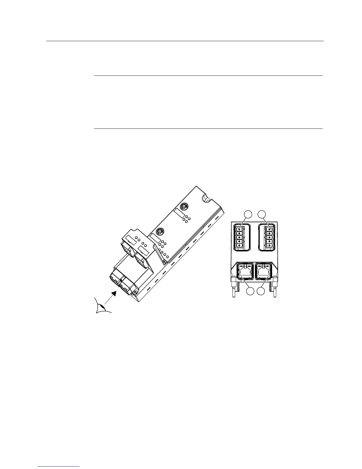
Connecting push-pull cable connectors
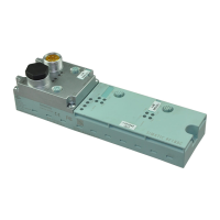
Plug the push-pull cable connectors for 1L+/2L+ and RJ-45 into the associated sockets (see
figure below). Ensure that the locking mechanism between the connector and socket is
properly applied. The connectors must engage.
6,0$7,&5)&
① X01 24 VDC Push-pull socket (with socket insert) for infeed of the 1L+ electronic/encoder
supply and the 2L+ load voltage supply
② X02 24 VDC Push-pull socket (with socket insert) for looping through of the 1L+
electronic/encoder supply and the 2L+ load voltage supply
④ X03 PN1 Push-pull socket for RJ-45 for feeding of PROFINET IO
③ X04 PN2 Push-pull socket for RJ-45 for looping through of PROFINET IO
Figure 4-5 Connecting push-pull cable connectors