Live Demo
Micro Automation Set 14 Entry ID 21062588
V2.0 05/18/05 20/35
Copyright © Siemens AG 2005 All rights reserved
Set14_DocTech_V2.0_en.doc
Configuring S7-200 “Backup” station with MicroWin project
Table 5-4
No. Function Comment
1.
Connect the S7-200 CPU to a DC 24V
power supply.
2.
Connect the configuration PC and S7-200
“Backup” with a USB/PPI cable via the
USB interface of the PC.
3.
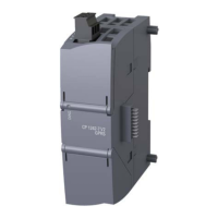
Plug the ribbon cable of CP 243-1 in the
interface at the S7-200 CPU.
4.
Plug the 256 KB memory cartridge in
the S7-200 CPU.
5. Switch on the power supply.
6.
Open the included S7-200 project
“Set14_S7-200_V2-0.mwp” on the
configuration PC using STEP 7
Micro/WIN and make the following
settings in STEP 7 Micro/WIN:
• Set the access point in “Set PG/PC
Interface” to “Micro/WIN Æ PC/PPI
cable(PPI)”
• Select the USB port in the properties
of the selected access point.
7.
Load the program to the S7-200 CPU and
restart the S7-200 CPU.
S7-200 CPU 222 CP 243-1
Configuration PC
PPI cable
S7-200 “Backu

 Loading...


