Configuration
Micro Automation Set 14 Entry ID 21062588
V2.0 05/18/05 8/35
Copyright © Siemens AG 2005 All rights reserved
Set14_DocTech_V2.0_en.doc
Layout diagram of Micro Automation Set 14 – S7-200 “Basis”
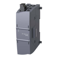
S7-200 “Basis” consists of an S7-200 CPU 222 (2) with clock cartridge
and Ethernet CP 243-1 (3) communications module. The Ethernet CP
243-1 is connected to SCALANCE X108 (4) via an Industrial Ethernet FC
standard cable with RJ45 plugs.
A LOGO! Power 1.3A (1) provides the power supply of the devices.
Note
SCALANCE X108 provides the option to additionally connect a redundant
power supply.
Layout diagram of Micro Automation Set 14 – S7-200 “Backup”
S7-200 “Backup” consists of an S7-200 CPU 222 (2) with 256 KB memory
cartridge and an Ethernet CP 243-1 (3) communications module. The
Ethernet CP 243-1 is connected to SCALANCE X108 (4) of the S7-200
“Basis” station via an Industrial Ethernet FC standard cable with RJ45
plugs.
A LOGO! Power 1.3A (1) provides the power supply of the devices.
230V~
Clock
24V
+ -
S7-200 “Basis”
2
1
3
4
S7-200 “Backup” S7-200 “Basis”
230V~
24V
+ -
256
2
1
3
4

 Loading...


