Assembling
4.4 Connecting
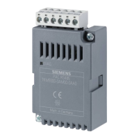
PAC RS485
24 Manual, 02/2008, A5E02091800B-01
SXOOXS
38
SXOOGRZQ
3'
&RPPRQ
*URXQG
%DODQFHG3DLU
0DVWHU
6ODYH 6ODYHQ
%
9
7(57(5
$
'
5
'
5
'
5
Figure 4-2 Block diagram: General topology of the twisted-pair cable
+/B B signal; D1
-/A A signal; D0
COM Common = Ground
TER (Line) Termination = bus terminating resistor
PU Pull-up resistor
PD Pull-down resistor
&RP % $ 7HU 38 3'
Figure 4-3 Terminal assignment
1. Connect the cables to the appropriate screw terminals on the terminal block. You can find
the assignments of the terminals in the figure "Terminal assignment".
2. Connect the cable shield at one end with protective ground PE.
3. Connect the signal Common with protective ground. This grounds the expansion module.
4. On the first and last communication nodes, switch a bus terminating resistor between the
positive signal and the negative signal. A 120-Ohm bus terminating resistor is
implemented in the PAC RS485 expansion module for this purpose. In the case of other
values, use an external bus terminating resistor. Attach this to the first and last
communication node.
 Loading...
