Alarm, error, and system messages
8.2 Diagnostics LED
PAC RS485
64 Manual, 02/2008, A5E02091800B-01
8.2 Diagnostics LED
Significance of the diagnostics LED
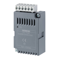
The diagnostics LED indicates the communication status.
Table 8-1 Fault and status indication by the LED
Color Status Description Measure
Green and
yellow
Off No voltage applied to the
PAC RS485 expansion module
1. Check that the PAC RS485 expansion
module is correctly connected to the
SENTRON PAC Power Monitoring Device.
2. Switch on the supply voltage to the
SENTRON PAC Power Monitoring Device.
Green Continuous
• Voltage applied to the
PAC RS485 expansion module
• The bus is not active.
-
Green Flashing Communication is active on the bus. -
Yellow Flashing The PAC RS485 expansion module
is sending data.
-
8.3 Initializing the module
Starting communication between the PAC RS485 expansion module and the SENTRON PAC Power
Monitoring Device
1. Power up
2. Initialization phase
3. Starting communication
The PAC RS485 expansion module is initialized. The SENTRON PAC Power Monitoring
Device is ready for communication.
The green LED lights continuously.
4. The master is sending data to the SENTRON PAC Power Monitoring Device.
The green LED flashes.
5. The SENTRON PAC Power Monitoring Device is forwarding data to the master.
The yellow LED flashes.
 Loading...
