EasyManuals Logo

Siemens SENTRON Series User Manual

Siemens SENTRON Series
40 pages
To Next Page IconTo Next Page
To Previous Page IconTo Previous Page
Page #12 background imageLoading...
Page #12 background image
Description
2.3 Design
Expansion module I(N), I(Diff), analog
12 Manual, 04/2017, L1V30408520AG-01
2.3 Design
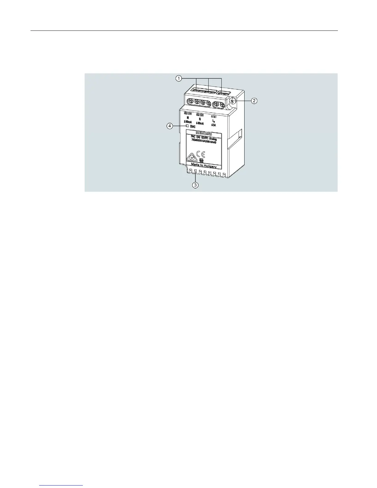
(1) Screw terminals for connection of current transformer or sensor
(2) Screw for mounting the expansion module I(N), I(Diff), analog
(3) Ventilation slot
(4) Diagnostic LED
Figure 2-1 Schematic representation of expansion module I(N), I(Diff), analog
I
N
connection:
Current transformer connection for N-conductor current measurement 1 A / 5 A input
I
5
connection:
0 ... 20 mA analog input
4 ... 20 mA analog input
0 ... 60 mA RCM (Residual Current Monitoring)
I
6
connection:
0 ... 20 mA analog input
4 ... 20 mA analog input
0 ... 60 mA PE current

Other manuals for Siemens SENTRON Series

Questions and Answers:

Question and Answer IconNeed help?

Do you have a question about the Siemens SENTRON Series and is the answer not in the manual?

Siemens SENTRON Series Specifications

General IconGeneral
Product SeriesSENTRON
CategoryMeasuring Instruments
Frequency Range45-65Hz
Communication InterfacesModbus RTU, Ethernet
DisplayLCD
Protection ClassIP20
Operating Temperature Range-10°C to +55°C
Storage Temperature Range-25°C to +70°C
Relative Humidity5% to 95% (non-condensing)
MountingDIN rail

Related product manuals