Special Features of the C7-613
3-3
C7-613 Control System
A5E00138934-03
When mode selection is enabled,
• you need to jumper the authorization inputs AT1 / AT2,
• The key LEDs alongside the operating mode keys indicate the mode selector
setting,
• The current CPU operating status is indicated by the status LEDs
When mode selection is disabled:
• You must leave the authorization inputs AT1 and AT2 open
• The key LEDs alongside the operating mode keys are switched off
• The current CPU operating status is indicated by the status LEDs
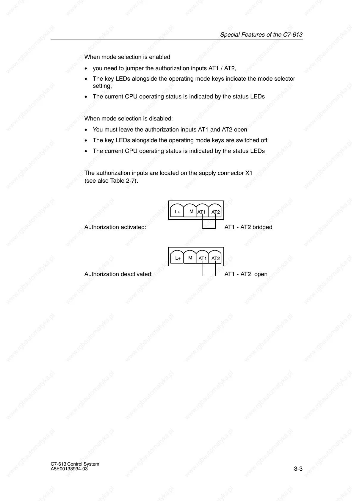
The authorization inputs are located on the supply connector X1
(see also Table 2-7).
Authorization activated:
AT2
AT1
M
L+
AT1 - AT2 bridged
Authorization deactivated:
AT2
AT1
M
L+
AT1 - AT2 open