Integration into the User Program
4-31
C7-613 Control System
A5E00138934-03
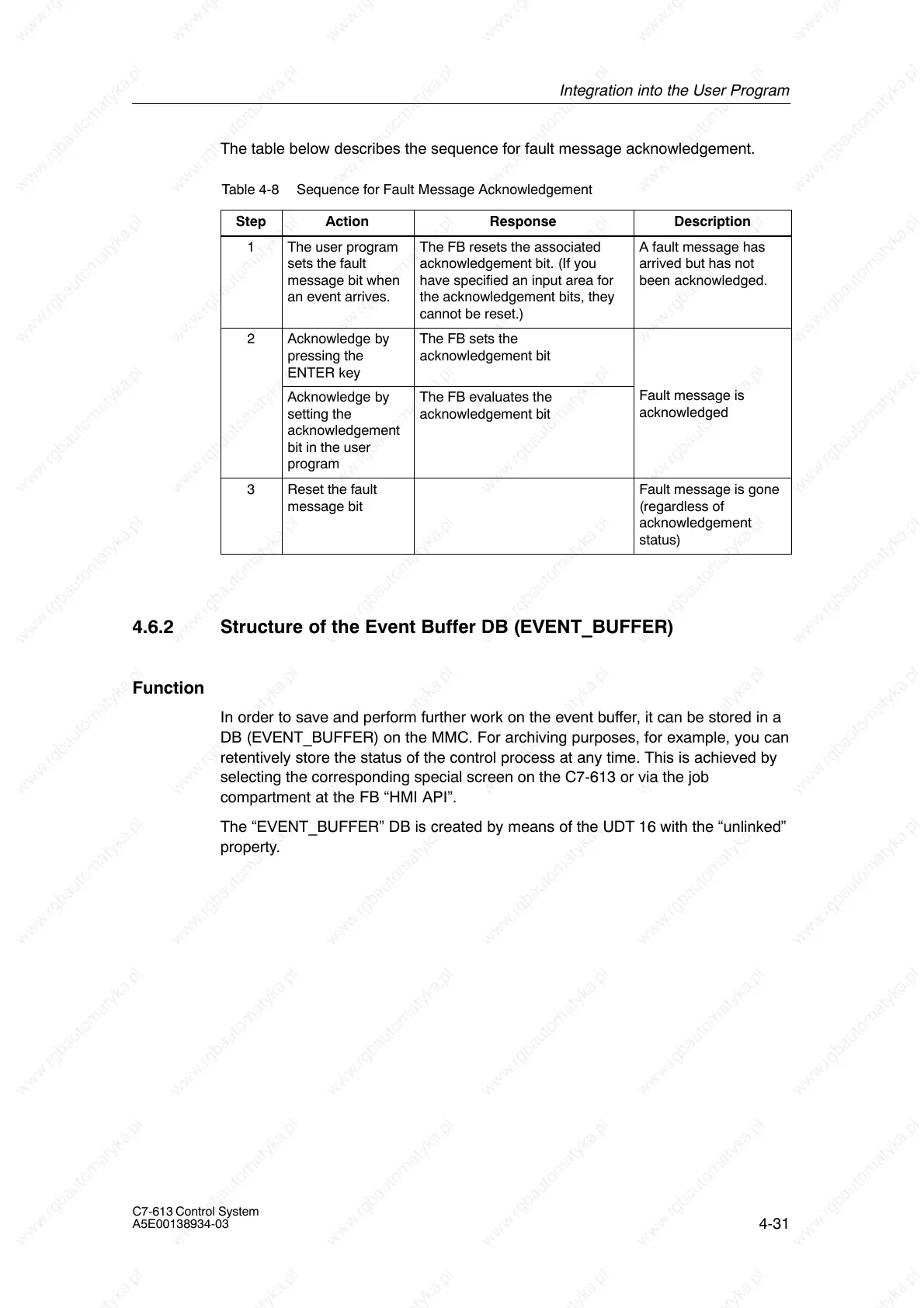
The table below describes the sequence for fault message acknowledgement.
Table 4-8 Sequence for Fault Message Acknowledgement
Step
Action Response Description
1 The user program
sets the fault
message bit when
an event arrives.
The FB resets the associated
acknowledgement bit. (If you
have specified an input area for
the acknowledgement bits, they
cannot be reset.)
A fault message has
arrived but has not
been acknowledged.
2 Acknowledge by
pressing the
ENTER key
The FB sets the
acknowledgement bit
Acknowledge by
setting the
acknowledgement
bit in the user
program
The FB evaluates the
acknowledgement bit
Fault message is
acknowledged
3 Reset the fault
message bit
Fault message is gone
(regardless of
acknowledgement
status)
4.6.2 Structure of the Event Buffer DB (EVENT_BUFFER)
Function
In order to save and perform further work on the event buffer, it can be stored in a
DB (EVENT_BUFFER) on the MMC. For archiving purposes, for example, you can
retentively store the status of the control process at any time. This is achieved by
selecting the corresponding special screen on the C7-613 or via the job
compartment at the FB “HMI API”.
The “EVENT_BUFFER” DB is created by means of the UDT 16 with the “unlinked”
property.