Special Features of the C7-613
3-5
C7-613 Control System
A5E00138934-03
3.2 Status and Error Displays of the C7-613
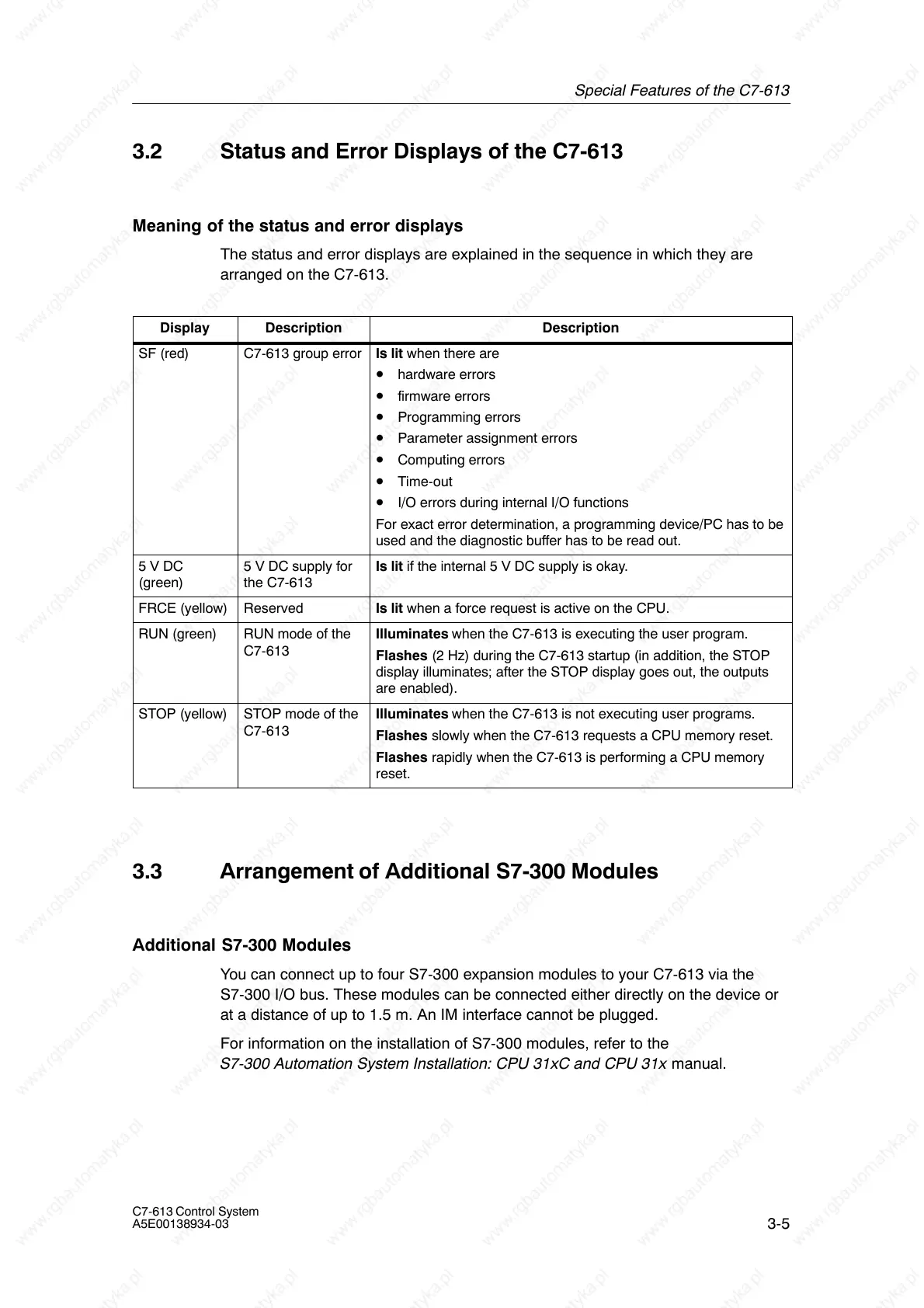
Meaning of the status and error displays
The status and error displays are explained in the sequence in which they are
arranged on the C7-613.
Display Description Description
SF (red) C7-613 group error Is lit when there are
• hardware errors
• firmware errors
• Programming errors
• Parameter assignment errors
• Computing errors
• Time-out
• I/O errors during internal I/O functions
For exact error determination, a programming device/PC has to be
used and the diagnostic buffer has to be read out.
5 V DC
(green)
5 V DC supply for
the C7-613
Is lit if the internal 5 V DC supply is okay.
FRCE (yellow) Reserved Is lit when a force request is active on the CPU.
RUN (green) RUN mode of the
C7-613
Illuminates when the C7-613 is executing the user program.
Flashes (2 Hz) during the C7-613 startup (in addition, the STOP
display illuminates; after the STOP display goes out, the outputs
are enabled).
STOP (yellow) STOP mode of the
C7-613
Illuminates when the C7-613 is not executing user programs.
Flashes slowly when the C7-613 requests a CPU memory reset.
Flashes rapidly when the C7-613 is performing a CPU memory
reset.
3.3 Arrangement of Additional S7-300 Modules
Additional S7-300 Modules
You can connect up to four S7-300 expansion modules to your C7-613 via the
S7-300 I/O bus. These modules can be connected either directly on the device or
at a distance of up to 1.5 m. An IM interface cannot be plugged.
For information on the installation of S7-300 modules, refer to the
S7-300 Automation System Installation: CPU 31xC and CPU 31x manual.