Integration into the User Program
4-24
C7-613 Control System
A5E00138934-03
Table 4-4 Relaying Key Operations, continued
Key RelayState C7-613
Function keys
Screen level Yes
(K-keys)
Screen level in input mode with cursor Yes
Screen level in input mode with K-keys No
Standard/special screen Yes
Standard/special screen in input mode
with cursor
Yes
Standard/special screen in input mode
with K-keys
No
Message level Yes
Output of a fault message Yes
Value Assignment
As long as the corresponding key is pressed, the assigned bit in the keyboard
image has the value 1; otherwise the value 0.
0
1
t
= Key is pressed
Bit value
The bit for the SHIFT key is set as long as the SHIFT LED is switched on.
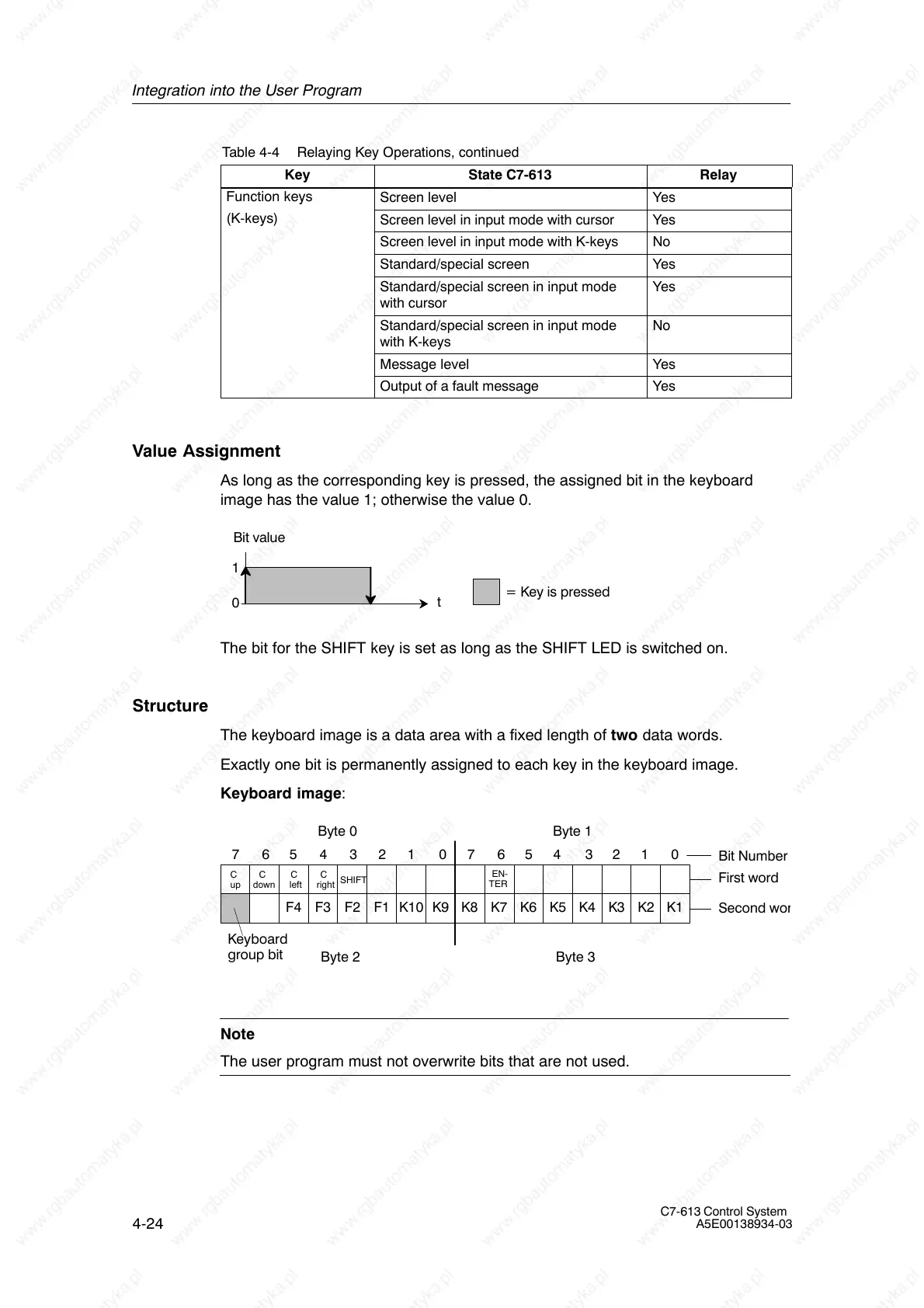
Structure
The keyboard image is a data area with a fixed length of two data words.
Exactly one bit is permanently assigned to each key in the keyboard image.
Keyboard image:
Bit Number
Byte 3
7654321076543210
K1K2K3K4K5K6K7K8K9K10F1F2F3F4
First word
Second wo
Byte 1
Byte 2
Byte 0
EN-
SHIFT
C
Keyboard
group bit
up
C
down
C
left
C
right
TER
Note
The user program must not overwrite bits that are not used.