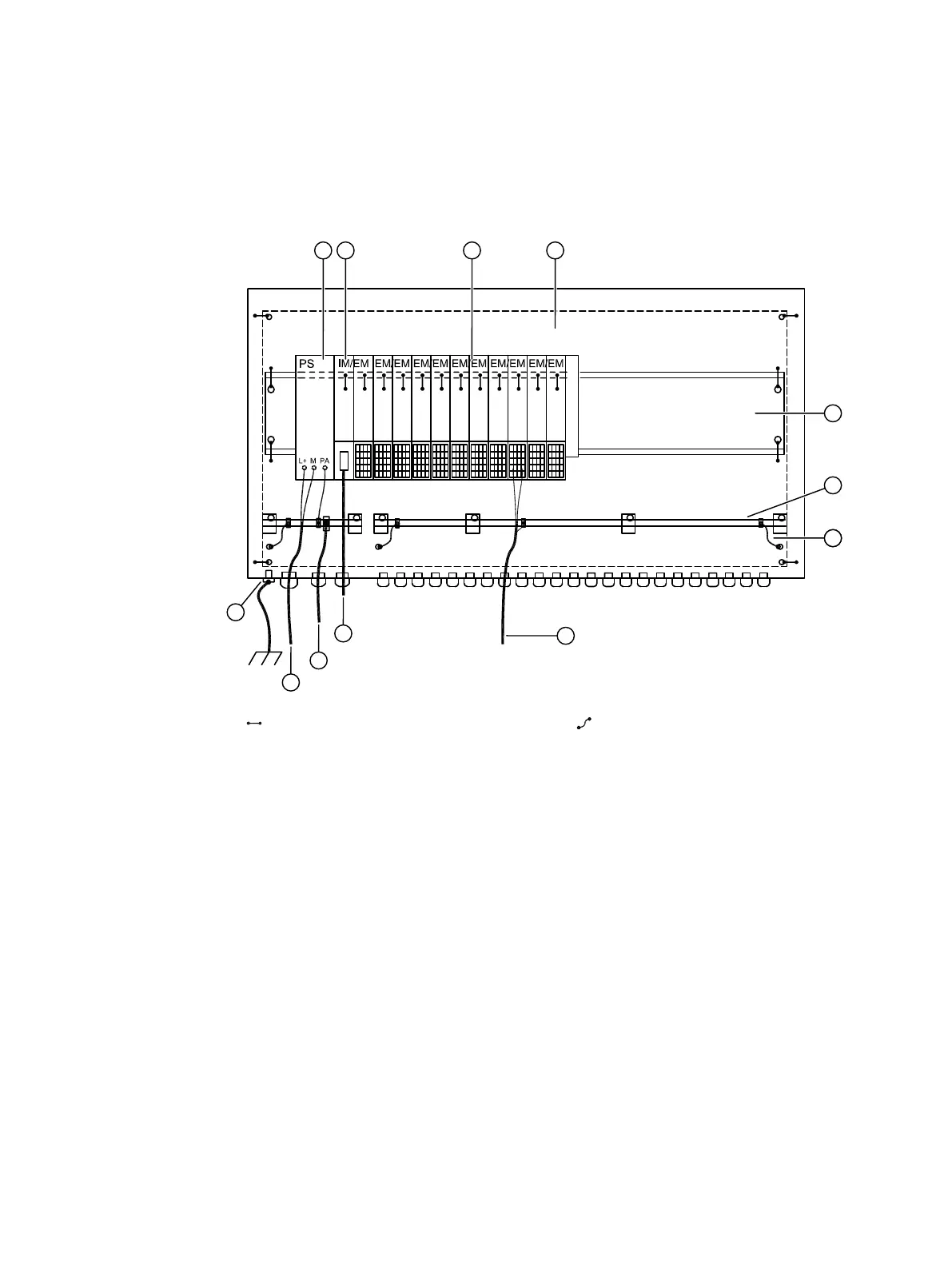
Ground points in the enclosure
9
Fixed galvanic electrical clamp or screw
terminal inside enclosure
Cable connection can be disconnected in‐
side enclosure
① Power supply terminal module with com‐
ponentry
⑦ Connection from the equipotential bond‐
ing rail to the enclosure
② IM / EM terminal module with IM compo‐
nentry (IM = interface module, EM = elec‐
tronic module)
⑧ Cable for signal lines shield on equipoten‐
tial bonding rail
③ EM / EM terminal module (EM = electronic
module)
⑨ PROFIBUS or PROFINET cable to IM
④ Mounting plate ⑩ Bonding cable
⑤ Mounting rail ⑪ Power supply (line to power supply)
⑥ Equipotential bonding rail with terminals ⑫ M6 grounding connection external
Figure9-1 Fixed and detachable connections to ground and equipotential bonding rail
Distributed I/O device 6DL2804-1xxxx & 6DL2804-2xxxx
Hardware Installation Manual, 11/2023, A5E42025214-AC 33

 Loading...


