Dimension drawings
10
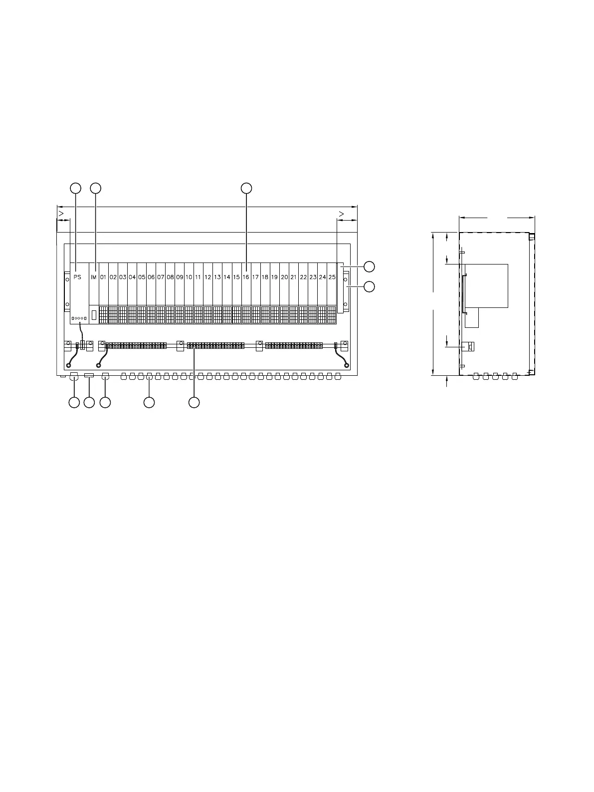
10.1 Installation: ET200iSP components
!
FD
① Power supply (PS)
terminal module
⑥ Equipotential bonding rail with terminals
② IM/EM terminal module with IM component
(IM = interface module, EM = electronic module)
⑦ Cable entry for signal cables M16 or M20
③ EM/EM terminal module with I/O component
(I/O = input/output)
⑧ M20 cable and conductor entry for PROFIBUS and PROFINET
④ Termination module ⑨ Screw gland for pressure/climate compensation
⑤ Mounting rail ⑩ Cable and conductor entries for PS M32
Figure10-1 Distributed I/O device 6DL2804-xxD/E with built-in ET200iSP
Distributed I/O device 6DL2804-1xxxx & 6DL2804-2xxxx
Hardware Installation Manual, 11/2023, A5E42025214-AC 35

 Loading...


