18-8
OP27,
OP37 Equipment Manual
Release 05/99
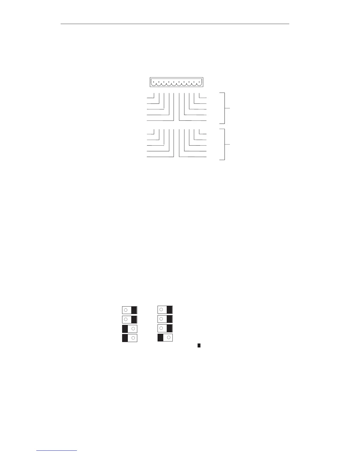
The
pin arrays of the module boards DKM A and DKM B have the following
pin assignment:
12345678910
GND
2
DO 8
DO 6
DO 4
DO 2
+24V DC ext.
DO 1
DO 3
DO 5
DO 7
DKM A
GND
2)
DO 16
DO 14
DO 12
DO 10
+24V DC ext.
DO 9
DO 11
DO 13
DO 15
DKM B
2)
Optocouplers electrically isolate the digital outputs from the OP.
The
components to be driven (e.g. relays, signaling indicators, etc.) are con
-
nected by means of the five-pin connectors supplied:
Connect the wires
(conductor cross-sections 0.5 to 2.5 mm
2
)
Seat
the terminal blocks on the pins of the DKM
The DIL switch setting determines how the digital outputs of the DKM are
controlled:
in the OFF position, by pressing function keys
in the ON position, by software
Software can control up to 16 DKM outputs, whereas only twelve can be con
-
trolled by function keys.
Setting the DIL switch:
DKM A DKM B
S1
S2
S3
S4
OFFON
S1 must always be set to ON
S2 selects the module board (DKM A
or DKM B)
S3 and S4 both act on one group of
outputs (refer to table)
S1
S2
S3
S4
OFFON
=
active switch setting
Pin
array
DIL switch
Options
Artisan Technology Group - Quality Instrumentation ... Guaranteed | (888) 88-SOURCE | www.artisantg.com
 Loading...


