18-15
OP27,
OP37 Equipment Manual
Release 05/99
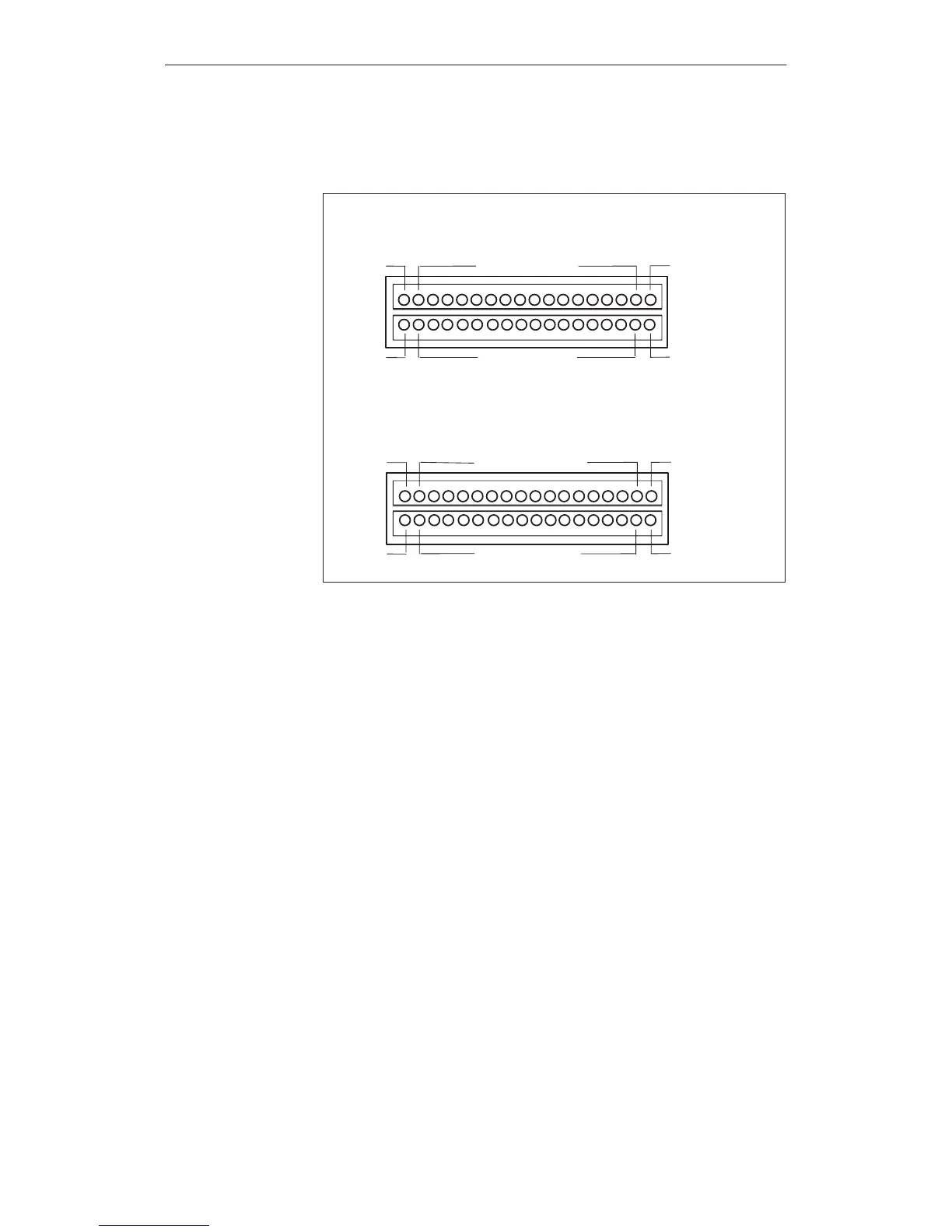
The
connectors of modules CPI 1 and CPI 2 have the following pin assign
-
ments:
+24V DC ext.
GND
1)
DO 16 to DO 1
CPI
1
CPI 2
+24V DC ext.
GND
)1
DI 16 to DI 1
+24V DC ext.
GND
1)
DO 32 to DO 17
+24V DC ext.
GND
1)
DI 32 to DI 17
1)
Non-floating
The controls and light indicators to be driven are connected by means of the
9-pin connectors supplied.
Make the cable terminal connections
(conductor cross-sections 0.5 to 2.5 mm
2
)
Seat the terminal blocks on the adapters of the CPI module boards.
Connector
Options
Artisan Technology Group - Quality Instrumentation ... Guaranteed | (888) 88-SOURCE | www.artisantg.com
 Loading...


