4-2
OP27,
OP37 Equipment Manual
Release 05/99
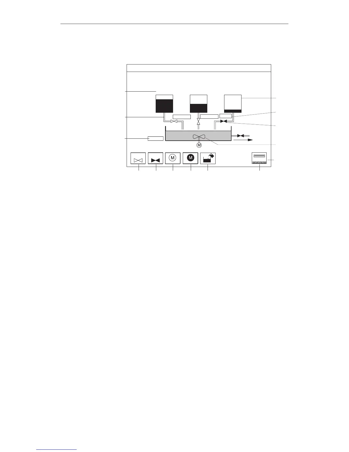
Figure
4-1 illustrates how the configured screen might appear on the OP
.
¬ Text
Character
graphics
®
Numeric output field
¯
Bar graph (tank load)
°
Symbolic input field for opening and closing the valve
±
Symbolic graphic indicates the status of the valve (open/closed)
² Graphic
³
Icons for soft-key functions
Mixing
Unit
T
ank 1
T
ank 2
T
ank 3
V
alve 4
Amount in
the mixer (l)
Valve
CLOSED
Valve
OPEN
Motor
OFF
Fill
tank
Selection
Main Screen
Motor
ON
44
5300
¬
®
¯
°
±
²
³
CLOSED
CLOSED
OPEN
Figure 4-1 Configured screen for a mixing unit (example)
Screens
can be viewed, processed and printed via the OP
. Before these actions
can be performed, however
, the screen has to be selected. Select a screen by
means of a
Function key
Pressing a function key opens the screen assigned to it in the configuration.
Input field
Enter the number of the screen to be opened in the input field.
PLC job
This is a special application provided to the operator. The PLC calls a
screen on the OP depending on the state of the process or the system, thus
specifying the procedure for the operator to follow
.
Selecting
a screen
Screens
Artisan Technology Group - Quality Instrumentation ... Guaranteed | (888) 88-SOURCE | www.artisantg.com
 Loading...


