Cycle and Response Times
7-7
ET 200S Interface Module IM 151/CPU
A5E00058783-01
Shortest Response Time
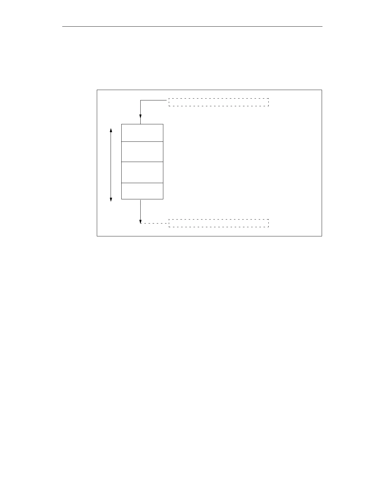
The following figure shows you the conditions under which the shortest response
time is obtained.
Operating
system
User
program
PII
The status of the observed input changes immediately
before reading in the PII. The change in the input
signal is therefore taken account of in the PII.
PIQ
The change in the input signal is processed
by the user program here.
The response of the user program to the input signal
change is passed on to the outputs here.
Response Time
Delay of the inputs
Delay of the outputs
Figure 7-2 Shortest Response Time
Calculation
The (shortest) response time consists of the following:
1 process image transfer time for the inputs +
1 operating system processing time +
1 program scanning time +
1 process image transfer time for outputs +
Execution time of S7 timer
Delay of the inputs and outputs
This corresponds to the sum of the cycle time and the delay of the inputs and
outputs.