Commissioning and Diagnostics
4-21
ET 200S Interface Module IM 151/CPU
A5E00058783-01
4.6.5 Module Status
Definition
The module status, as a particular form of module diagnosis, indicates the status
of the configured address areas of the intermediate memory and expands on the
module diagnosis. The module status starts after the module diagnosis and varies
in length according to the number of configured address areas.
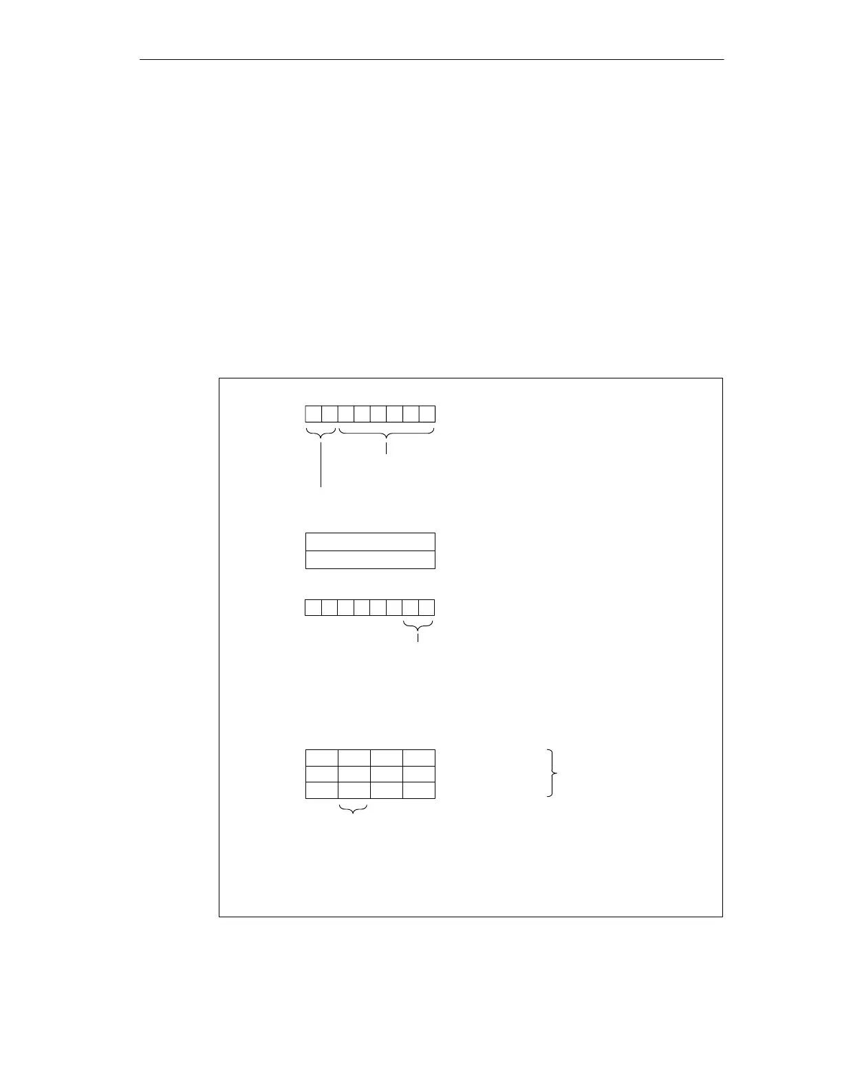
Structure
The module status of IM 151/CPU is structured as follows:
Byte (x+1)
Byte (x+2)
70
Byte (x+3)
70
82
H
0
H
76 54 132 0
Byte (x+5)
Byte (x+4)
Bit no.
Modules 1 to 4
Byte (x+...)
Modules 5 to 32
Byte (x+12)
Modules 33 to 35
00
B
: Module o.k.; valid user data
Module 2 (= CPU): CPU in RUN
01
B
: Module o.k.; invalid user data
Module 2 (= CPU): CPU in STOP
10
B
: Incorrect module; invalid user data
11
B
: No module (or module failure); invalid user data
Status
type:
Module
status
not
relevant
70
Bit no.
Code for the station diagnosis
00
6
Length of the module status including byte (x+1)
(depends on the number of configured address areas)
1
23
4
1
Bit no.
Bit no.
Status specification:
00
B
: No further differentiation
11
B
: Reserved
10
B
: Outgoing
01
B
: Incoming
333435
... ... ......
000000
Modules 1 to 3:
Modules of the CPU
Modules 4 to 35:
Configured address areas,
i.e.: module 4 is the 1st
configured address area
Figure 4-5 Structure of the Module Status