Commissioning and Diagnostics
4-22
ET 200S Interface Module IM 151/CPU
A5E00058783-01
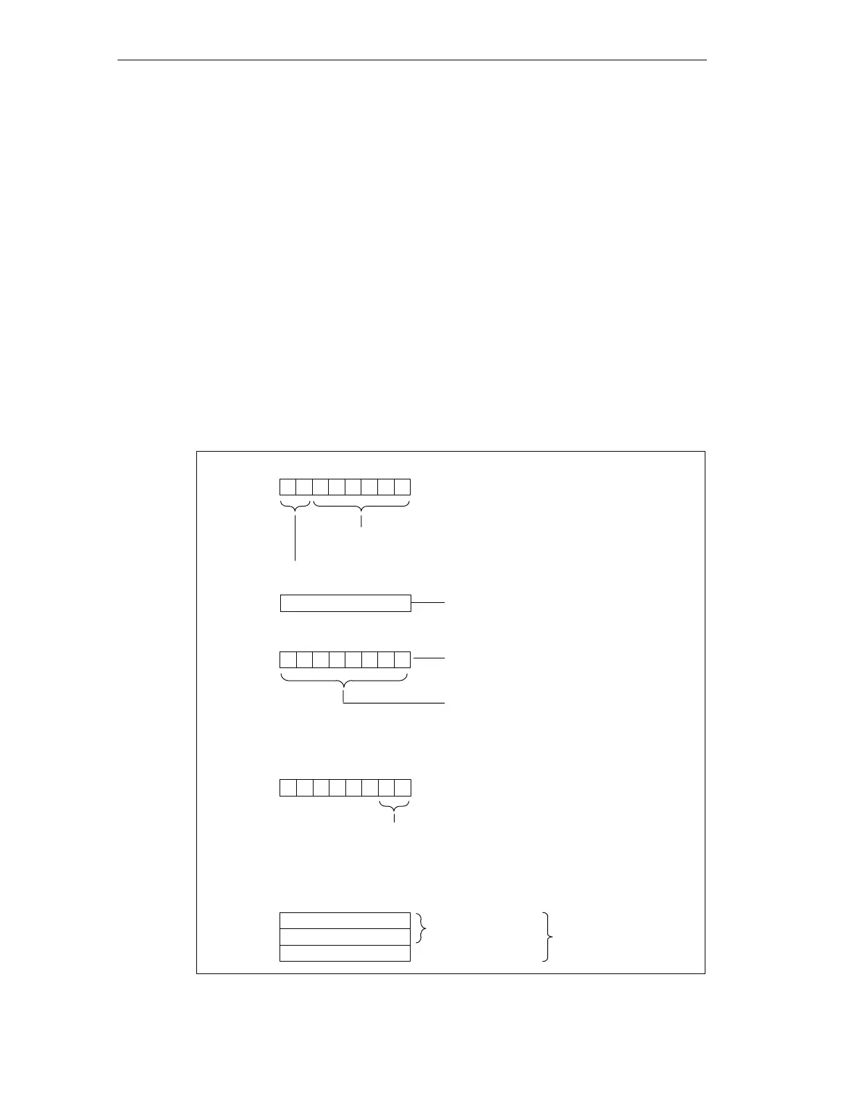
4.6.6 Structure of the Station Diagnosis
The device-specific diagnosis is only issued in S7 slave operating mode.
Definition
The station diagnosis provides detailed information on a DP slave. The station
diagnosis starts after the module status and contains a maximum of 20 bytes for
the IM 151/CPU, depending on the slave operating mode and the parameter
assignment frame.
The following generally applies: If an error occurs, the corresponding bit is set to “1”.
Structure
The figure below illustrates the structure and contents of the bytes for the
IM 151/CPU.
Byte (y+2)
01
H
: Code for diagnostic interrupt
02
H
: Code for process interrupt
Byte (y+5)
Byte (y+1)
70
Bit no.
Length of the station diagnosis including byte y+1:
8 bytes for the process interrupt and 20 bytes for the
diagnostic interrupt
Code for the station diagnosis
00
6
Byte (y+3)
Number of the configured address
area in the intermediate memory
Additional interrupt
information
for process interrupt
70
00
000001
e.g.
Bit no.
Valid: Number+3
70
Byte (y+4)
1 Bit no.
Interrupt
specification:
0:
no
further
differentiation
3:
Reserved
2:
Outgoing
1:
Incoming
000000
Up to (y+8)
Up to (y+20)
Diagnostic data
for diagnostic
interrupt
Example: CPU = 02
H
1st address area = 04
H
2nd address area = 05
H
etc.
Figure 4-6 Structure of the Station Diagnosis (1)