Commissioning and Diagnostics
4-15
ET 200S Interface Module IM 151/CPU
A5E00058783-01
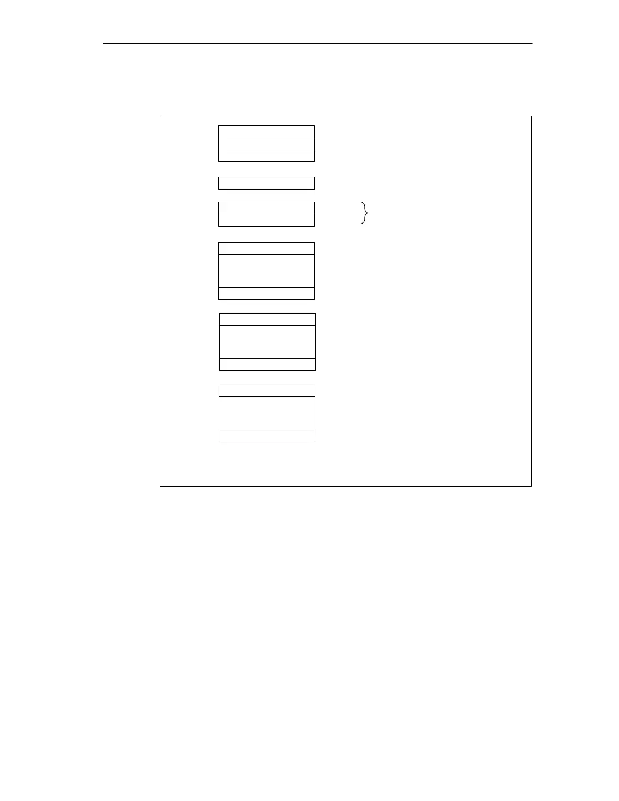
Structure of the Slave Diagnostic Data
Byte 0
Byte 1 Station Status 1 to 3
Byte 2
Byte 3 Master PROFIBUS Address
Byte 4
Byte 5 Low byte
High byte
Manufacturer ID
Byte 6
to
Module Diagnostics
Byte x
Station Diagnostics
.
.
.
.
.
.
Byte x+1
to
Byte y
(the length depends on the
number of address areas
configured for the intermediate
memory
1
)
(the length depends on the type
of interrupt)
1
Exception: If the DP master is incorrectly configured, the DP slave
interprets 35 configured address areas (46
H
in byte 6).
.
.
.
Byte y+1
to
Byte z
(the length depends on the
number of configured address
areas)
Module Status
Figure 4-3 Format of the Slave Diagnostic Data