Technical Specifications
6-4
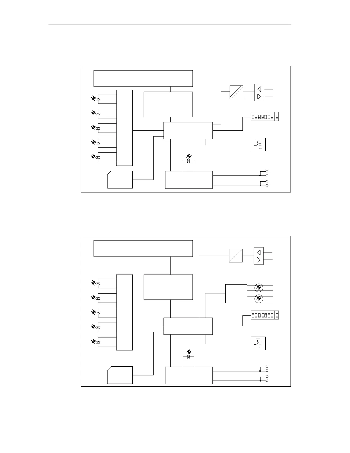
ET 200S Interface Module IM 151/CPU
A5E00058783-01
Basic Circuit Diagram for the IM 151/CPU
L+
M
Internal power
supply
A
B
PROFIBUS-DP connection
(RS485)
Galvanic
isolation
PROFIBUS
address
ON
CPU
(P, ROM, RAM)
Mode selector
MRES
RUN-P
STOP
MMC
ET 200S
backplane bus
interface module
Backplane bus
Electronics
FRCE
BF
SF
RUN
STOP
Figure 6-1 Basic Circuit Diagram for the IM 151/CPU
Basic Circuit Diagram for the IM 151/CPU FO
L+
M
Internal power
supply
PROFIBUS
address
ON
CPU
(P, ROM, RAM)
Mode selector
MRES
RUN-P
STOP
MMC
PROFIBUS-DP connection
(fiber-optic cable)
Fiber-op-
tic inter-
face
A
B
A
B
ET 200S
backplane bus
interface module
Backplane bus
Electronics
FRCE
BF
SF
RUN
STOP
A
B
PROFIBUS-DP connection (RS485)
Figure 6-2 Basic Circuit Diagram for the IM 151/CPU FO