*HWWLQJ6WDUWHG
Getting Started - ET 200S-IM 151/CPU Interface Module
A5E00058783-01
8-5
6WHS3XWWLQJWKH(76,0&38LQWR2SHUDWLRQ
6WDJH 'HVFULSWLRQ
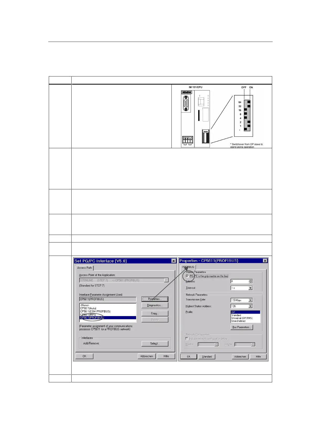
1 Make sure that the mode selector is at
STOP
.
Switch on the lowest DIP switch (for stand-
alone operation) and the 4th DIP switch from
the bottom (for PROFIBUS-DP address 4) on
the IM 151/CPU.
Make sure that the other DIP switches are off.
2 Switch on the PS of the IM 151/CPU.
Result:
• The
DC24V
LED lights up on the PS.
• The
PWR
and the
SF
LED light up on the PM.
• All the LEDs light up on the IM 151/CPU, the
BF
and the
RUN
LEDs go out, and the
STOP
LED begins to flash slowly. The IM 151/CPU is thus requesting a memory reset.
3 Briefly press down the mode selector of the IM 151/CPU to MRES. The
STOP
LED begins to
flash rapidly and then comes on continuously. This indicates that the memory reset has been
completed.
The
SF
LEDs on the PM and IM 151/CPU go out.
4 Operate the two switches connected to the DI. When you operate the switch on terminals 1
and 3, the
1
LED lights up.
When you operate the switch on terminals 5 and 7, the
5
LED lights up.
5 Switch on your programming device, and start SIMATIC Manager on the Windows desktop.
6a Click Options in SIMATIC Manager, and then choose the Setting PG/PC Interface menu
command. Configure the programming device/PC interface as follows:
6b
Note: The communication processor may have a different name in your programming device.
Make sure that the PROFIBUS version is set.
7 Apply the settings with OK, and close the Setting the PG/PC Interface program.