Instruction List
B-25
ET 200S Interface Module IM 151/CPU
A5E00058783-01
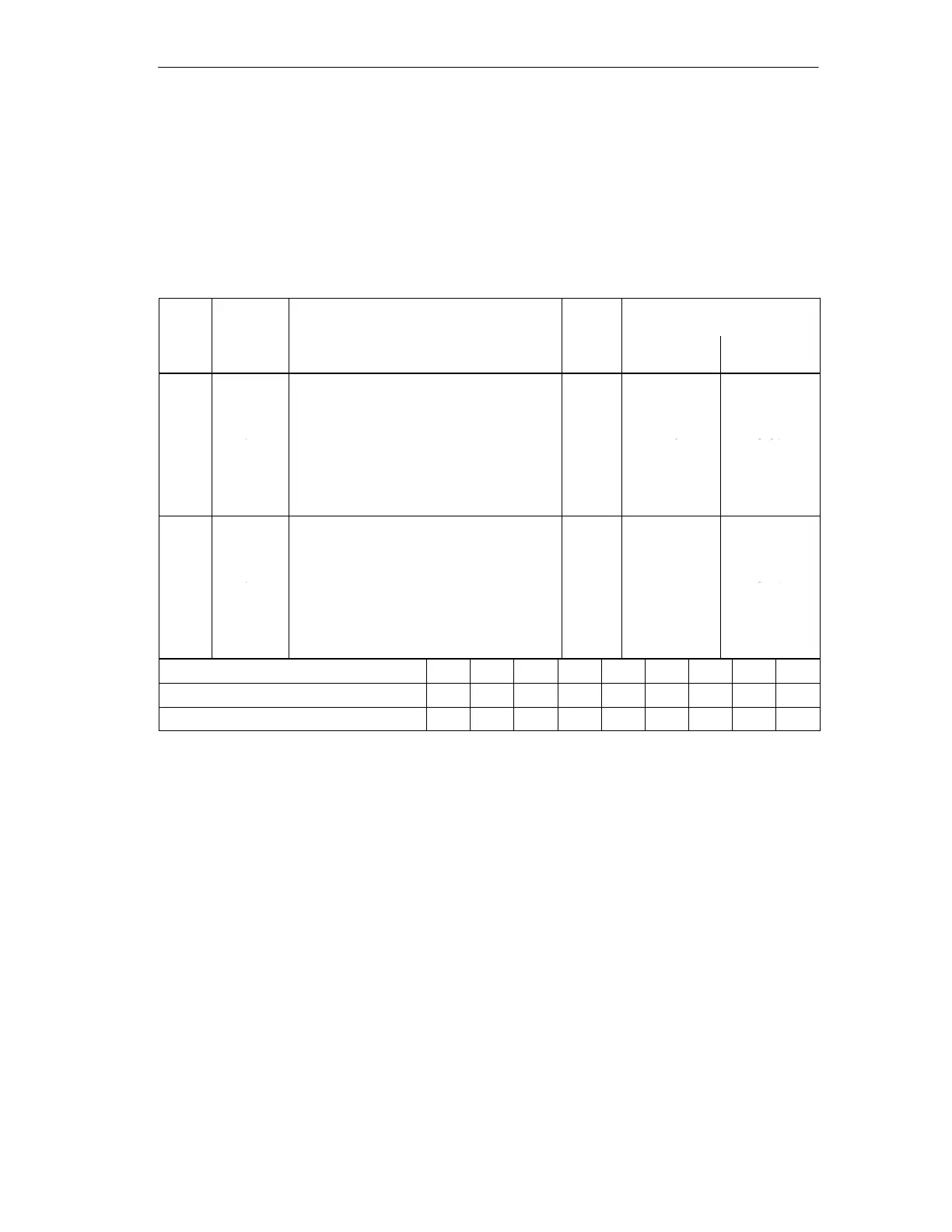
B.12 Edge-Triggered Instructions
Detection of an edge change. The current signal state of the RLO is compared with
the signal state of the instruction or ”edge memory marker”.
FP detects an edge change from ”0” to ”1”.
FN detects an edge change from ”1” to ”0”.
In-
stru-
Address
Length
in
Typical Execution Time in
s
ction
ID
Description
Words
Direct Ad-
dressing
Indirect Ad-
dressing
*
FP I/O
M
L
DBX/DIX
Detection of the rising edge in the RLO.
The bit addressed in the instruction is the
auxiliary edge memory marker.
2 0.8
1.5
1.6
4.0
2.4+
2.7+
2.7
3.6+
[AR1,m]
[AR2,m]
Parame-
ters
–
–
–
+
+
+
FN I/O
M
L
DBX/DIX
Detection of the falling edge in the RLO.
The bit addressed in the instruction is the
auxiliary edge memory marker.
2 1.0
1.6
1.7
4.1
2.6+
2.8+
2.8+
3.7+
[AR1,m]
[AR2,m]
Parame-
ters
–
–
–
+
+
+
Status word for: FP, FN BR A1 A0 OV OS OR STA RLO /FC
Instruction depends on: – – – – – – – Yes –
Instruction controls: – – – – – 0 Yes Yes 1
* + time for loading the address of the instruction