Functions
3.1 Option handling with RESERVE modules
Interface module IM151-1 STANDARD (6ES7151-1AA06-0AB0)
22 Manual, 07/2015, A5E01075950-AD
The control and feedback interface is located in the input and output process image of the
PM-E 24..48 VDC or PM-E 24..48 VDC/24..230 VAC power module. It can only be accessed
if entries ending in ...O or ...SO for that power module were selected in the configuration
software.
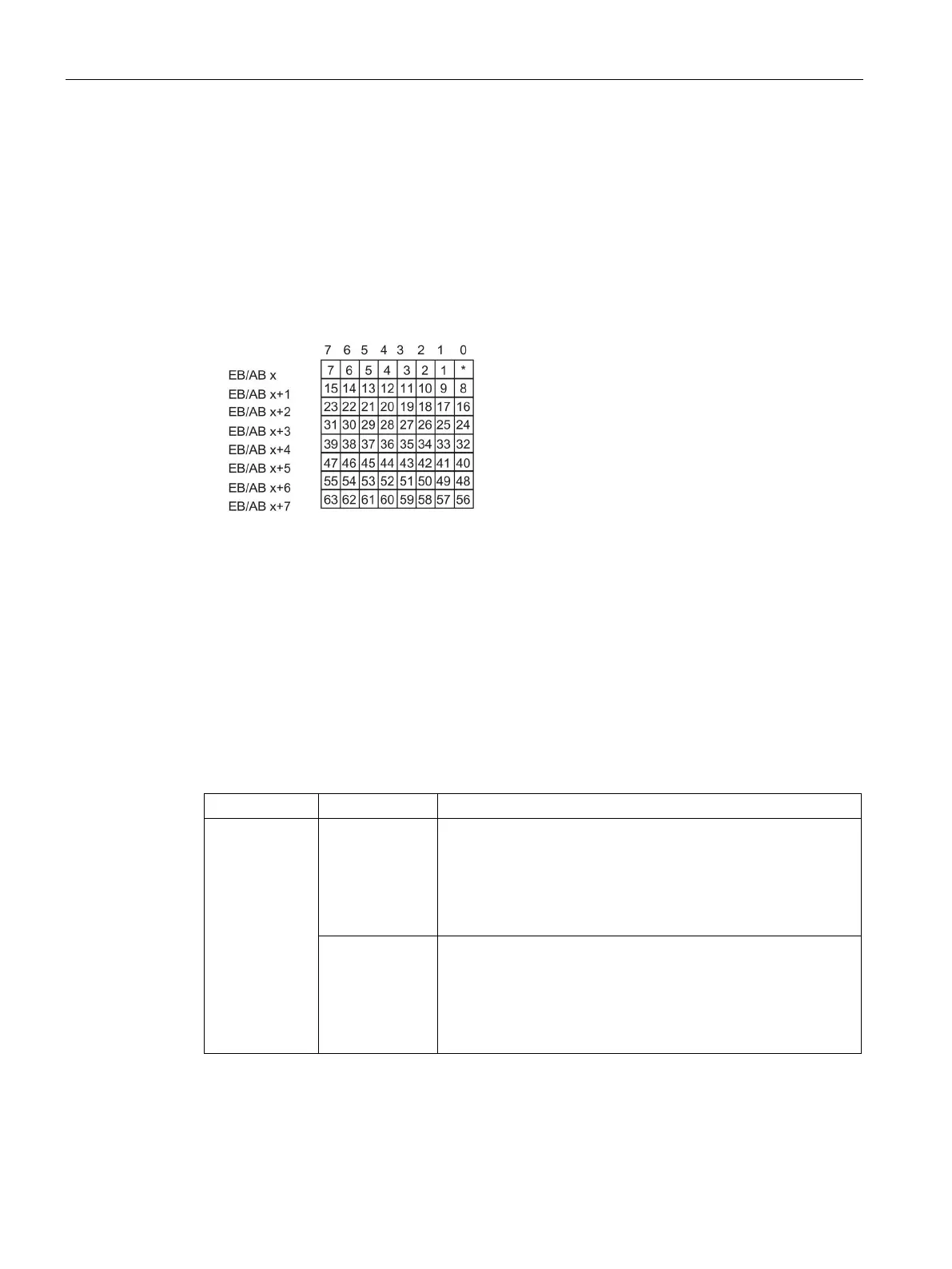
One bit is available for each ET 200S electronic or RESERVE module slot.
● Control interface: Slot 2 to 63
● Feedback interface: Slot 1 to 63
Figure 3-3 Control (PIQ) and feedback interface (PII)
Control interface PIQ (AB x to AB x+7):
You can use these bytes (8 bytes) to control the diagnostic behavior of the slots that you
enabled for option handling in the HW Config.
Only the slot bits enabled at parameter assignment for option handling are evaluated. They
are marked with "0".
Table 3- 1 Control interface
2 to 63 0 Parameter assignment for option handling applies. RESERVE
modules are allowed:
• The station is engaged in data exchange.
• A diagnostic is not signaled.
• The SF LED on the interface module is off.
1 Parameter assignment for option handling is cancelled.
RESERVE modules are not accepted on this slot:
• The station is engaged in data exchange.
• The diagnostic "Incorrect module" is signaled.
• The SF LED on the interface module is on.

 Loading...


