Interrupt, error, and system messages
4.5 Evaluating the interrupts of the ET 200S
Interface module IM151-1 STANDARD (6ES7151-1AA06-0AB0)
58 Manual, 07/2015, A5E01075950-AD
Evaluating hardware interrupts with
STEP 7
When a process interrupt occurs, the CPU interrupts the processing of the user program and
processes the OB 40 process interrupt block.
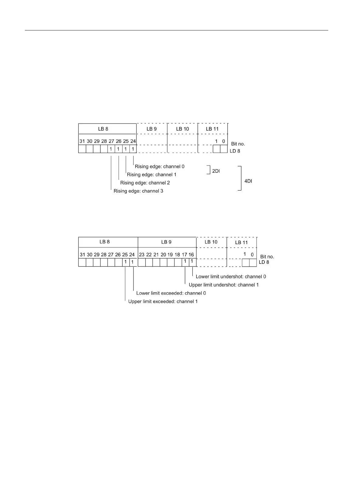
The module channel that triggered the process interrupt is entered in the start information of
OB 40, in the OB40_POINT_ADDR variable. The figures below show how the local data
double word 8 is assigned to the bits.
Process interrupts in electronic modules 2DI DC24V HF and 4DI DC24V HF:
Figure 4-13 OB 40 start information: The event that triggered the process interrupt for digital input
modules
Process interrupts for 2 AI U HS, 2 AI I 2WIRE HS and 2 AI I 4WIRE HS electronic modules:
Figure 4-14 OB 40 start information: The event that triggered the process interrupt for analog input
modules
You will find a description of OB 40 in the
System and Standard Functions
Reference
Manual.
Triggering a insert/remove module interrupt
Insert/remove-module interrupts are supported in DPV1 mode. The CPU interrupts
processing of the user program and processes diagnostic block OB 83 instead. The event
that triggered the interrupt is entered in the OB 83 start information.

 Loading...


