Technical specifications
8.6 Hardware descriptions
SIMATIC IPC427D
Operating Instructions, 05/2017, A5E31347215-AB
135
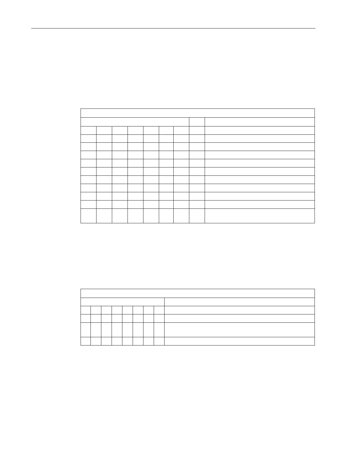
Output register user LED L1/L2/L3 (read/write, address 404Eh)
Meaning of the bits
The "PC ON/WD" LED flashes yellow to indicate the progress of the BIOS self-test during
device startup. After the BIOS self-test has been completed, the "PC ON/WD" LED lights up
continuously green.
Output register L1/L2/L3 (read/write, address 404Eh)
15 14 13 12-8 7 6 5 4-0
LED L1 / Run/Stop dark (default)
LED L1 / Run/Stop lit yellow
LED L1 / Run/Stop lit green
LED L2 / SF dark (default)
1 0 LED L2 / SF lit yellow
LED L3 / Maint dark (default)
LED L3 / Maint lit yellow
xxxx
xxxx
Reserved (read/write)
Battery status register (read-only, address 50Ch)
The status of the CMOS battery is monitored; the status (two-tier) can be read from the
battery status register.
Battery status register (read-only, address 50Ch)
CMOS battery capacity is still sufficient.
1 0 CMOS battery capacity is exhausted (remaining capacity is
sufficient for approx. one month)