EasyManuals Logo

Siemens SIMATIC NET S7-300 User Manual

Siemens SIMATIC NET S7-300
317 pages
To Next Page IconTo Next Page
To Previous Page IconTo Previous Page
Page #163 background imageLoading...
Page #163 background image
6 Programmed Communication Connections
A-163
S7-CPs for Industrial Ethernet Configuring and Commissioning
Release 01/2007
C79000-G8976-C182-07
6.2 Procedure
Initial Situation
The steps described here assume the following:
1. You have created the local S7 station and the required partner stations in your
STEP 7 projects (refer to the description in Chapter 3).
2. You have clarified the other station types with which connections must be
established. You create substitute objects for these station types in your
STEP 7 projects.
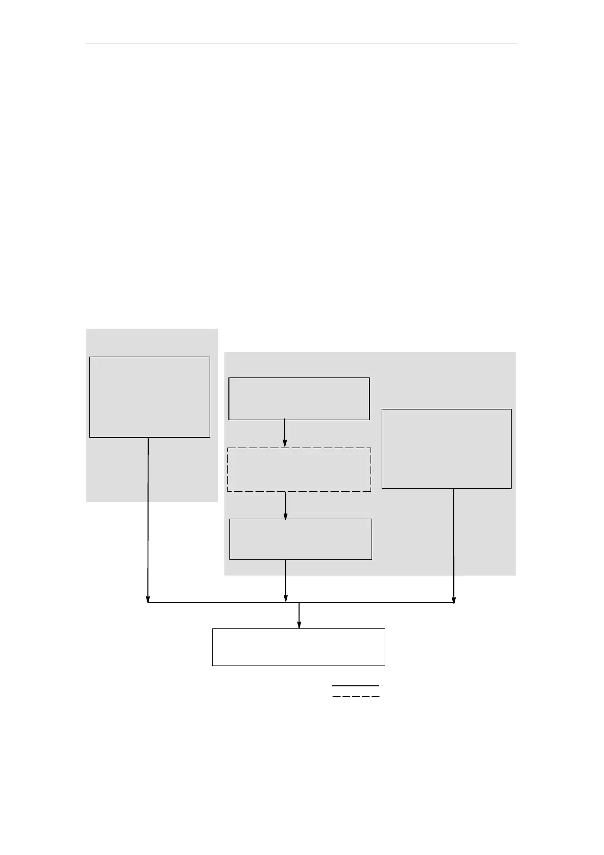
Setting up Connections and Using Them in the User Program
Follow the steps outlined below to set up connections on the SIMATIC S7 PLC
using the user program:
Program the
SEND/RECEIVE interface in
the user program.
(Refer to Section 4.2 and the
detailed FC description in
Chapter 7).
Download configurations and user
programs to the S7 station.
Configuring
necessary steps
optional steps
Legend:
Programming
Set the CP Properties in
the “IP Configuration” tab:
Select the “Set IP
address in user program”
option.
Create system data and
connections in the configuration
DB
Specify the connection
characteristics in the
Configuration DB.
Program FB interface in the
user program.

Table of Contents

Other manuals for Siemens SIMATIC NET S7-300

Questions and Answers:

Question and Answer IconNeed help?

Do you have a question about the Siemens SIMATIC NET S7-300 and is the answer not in the manual?

Siemens SIMATIC NET S7-300 Specifications

General IconGeneral
Product Type DesignationSIMATIC NET S7-300
MountingDIN rail mounting
Protection ClassIP20
CPU ModelsVarious models available (e.g., CPU 312, CPU 314)
Communication InterfacesMPI, PROFIBUS DP
Power Supply24 V DC power supply required. Different power supply modules available.
I/O ModulesDigital input modules, digital output modules, analog input modules, analog output modules
ProgrammingSTEP 7 software
Supply Voltage24V DC or 120/230V AC (depending on model)
Digital InputsAvailable via digital input modules
Digital OutputsAvailable via digital output modules
Analog InputsAvailable via analog input modules
Analog OutputsAvailable via analog output modules
Communication FunctionsMPI, PROFIBUS DP, Ethernet (depending on model)
ProtocolsMPI, PROFIBUS DP, TCP/IP (depending on model)
Operating Temperature0°C to 60°C
Storage Temperature70 °C
MemoryDepends on CPU model (e.g., 32 KB to 1.5 MB)

Related product manuals