Detailed descriptions
17.1 Motherboard
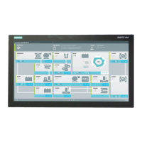
SIMATIC Panel PC 877
Operating instructions, Release 07/2006, A5E00877780-01
17-21
Interface to floppy disk drive, X26
This interface is designed for connecting a standard floppy drive. The maximum length of the
data cable should not exceed 40 cm.
Pin No. Abbreviation Meaning Input/Output
1 GND Ground -
2 DENSEL High density disk selection Output
3 GND Ground -
4 - Not assigned -
5 GND Ground -
6 DRAME0 Data rate signal Output
7 GND Ground -
8 INDEX_N Index hole recognition Input
9 GND Ground -
10 MOT_N0 Activate motor 0 Output
11 GND Ground -
12 DS_N1 Drive 1 selection -
13 GND Ground -
14 DS_N0 Drive 0 selection -
15 GND Ground -
16 MOT_N0 Activate motor 1 Output
17 GND Ground -
18 DIR_SL_N Step motor direction Output
19 GND Ground -
20 STEP_N Step motor pulse -
21 GND Ground -
22 WR_DAT_N Write data signal Output
23 GND Ground -
24 WR_GAT_N Enable data signal Output
25 GND Ground -
26 TRACK_N0 Track 0 signal Input
27 GND Ground -
28 WR_PRT_N Write protection signal Input
29 GND Ground -
30 RD_DAT_N Read data signal Input
31 GND Ground -
32 SIDE_1_N Page selection Output
33 MED_ID1 High density disk recognition Input
34 DCHG_N Disk change display Input