Hardware Overview
1-23
SIMATIC PCS 7 OSx 4.0.0 Hardware (PA RISC)
1.13 Connecting Options: S7-200 CPU 212 Alarm Option
The S7-200
CPU 212
provides
connection to a failover circuit and to
external warning and critical alarm annunciators.
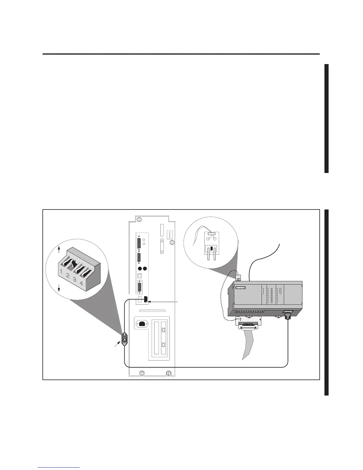
Figure 1-8
shows how the
PC/PPI cable connects the system unit to the S7–200 and the S7–200 to the
failover cable.
1.
Refer to
Figure 1-8
to set the dipswitches on the PC/PPI cable for a
baud rate of 9600.
2.
Connect the PC end of the PC/PPI cable to serial port 1 of the system
unit; connect the PPI end of the cable to the S7–200.
3.
Connect the failover circuit adapter to the output connector at the
bottom of the S7–200. Connect the two-pronged end of the twisted wire
to the leftmost sockets (1L and 0.0) on the input connector at the top of
the S7–200. Be sure that the prongs face to the front of the S7–200.
Refer to
Appendix A
for information about configuring the failover circuit
and external alarms.
S7–200
CPU 212
12
Switch
Serial Port 1
Failover Circuit
Adapter
RS–232
RS–485
Power Cable
DIP switch settings (down = 0, up = 1):
0 1 0 0 = 9600 baud
1
0
PC/PPI Cable
Ribbon Cable
Failover
Circuit
Figure 1-8 Connecting the OSx Station to the S7–200 CPU 212
 Loading...


