Application planning
6.2 Installation location
SIMATIC PN/CAN LINK
80 Operating Instructions, 03/2022, A5E39895388-AC
6.2 Installation location
Selection of the installation site / mounting position
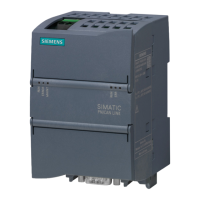
You can install the PN/CAN LINK either in a control panel or on a standard mounting rail:
Permitted mounting positions and permitted ambient temperature
The table below show the permitted temperature range for the different mounting positions.
Permitted ambient temperature
Ensure that condensation is not produced at a relative humidity between 10% and 95%.
Ensure that the atmospheric pressure is between 795 hPa and 1080 hPa. This corresponds to
an installation height of -1000 m to +2000 m.
The PN/CAN LINK is designed for natural heat dissipation through convection. Therefore
observe sufficient clearances:
• For horizontal mounting position: At least 35 mm above and below the PN/CAN LINK
• For vertical mounting position: At least 35 mm to the left and right of the PN/CAN LINK
Provide sufficient space for the connection of supply voltage, Ethernet and CAN bus.
 Loading...
