Connecting
8.3 24 V DC power supply
SIMATIC PN/CAN LINK
Operating Instructions, 03/2022, A5E39895388-AC
89
8.3 24 V DC power supply
24 V DC power supply
The connection of the external 24 V power supply and the functional earth connection takes
place via a 3-pin screw-type terminal. It is located below the top housing cover (see Design
(Page 32)).
A suitable power supply is, for example, SIMATIC S7-1200 Power Supply PM1207 (6EP1332-
1SH71).
Safety information
Connection only over safety extra-low voltage / protective extra-low voltage
May cause death or serious injury
The device is designed for operation using directly connectable safety extra-low voltage
(SELV) with safe electrical separation according to IEC 60950-1 / EN 60950-1 / VDE 0805-1
or IEC 61131-2 / EN 61131-2 / DIN EN 61131-2.
To maintain the safety property of the low voltage circuits of the PN/CAN LINK, the 24 V
rated power supply as well as external connections to communication ports must be
supplied from reliable sources that meet the requirements for SELV / PELV limited voltage
sources according to different standards.
Therefore only connect safety extra-low voltages (SELV) with safe electrical separation
according to IEC 60950-1 / EN 60950-1 / VDE 0805-1 to the supply voltage connections and
the communications interfaces.
Connector pin assignment
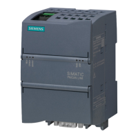
The figure below shows the assignment of the terminal for the 24 DC power supply.
Table 8- 1 Terminal assignment for the 24 DC power supply
24 V supply for PN/CAN LINK (+)
24 V supply for PN/CAN LINK (-)
Permissible torques for screw terminal:
• Minimum tightening torque: 0.5 Nm
• Maximum tightening torque: 0.6 Nm
 Loading...
