6
6-20
Working with S5-DOS/ST
C79000-G8576-C760-03
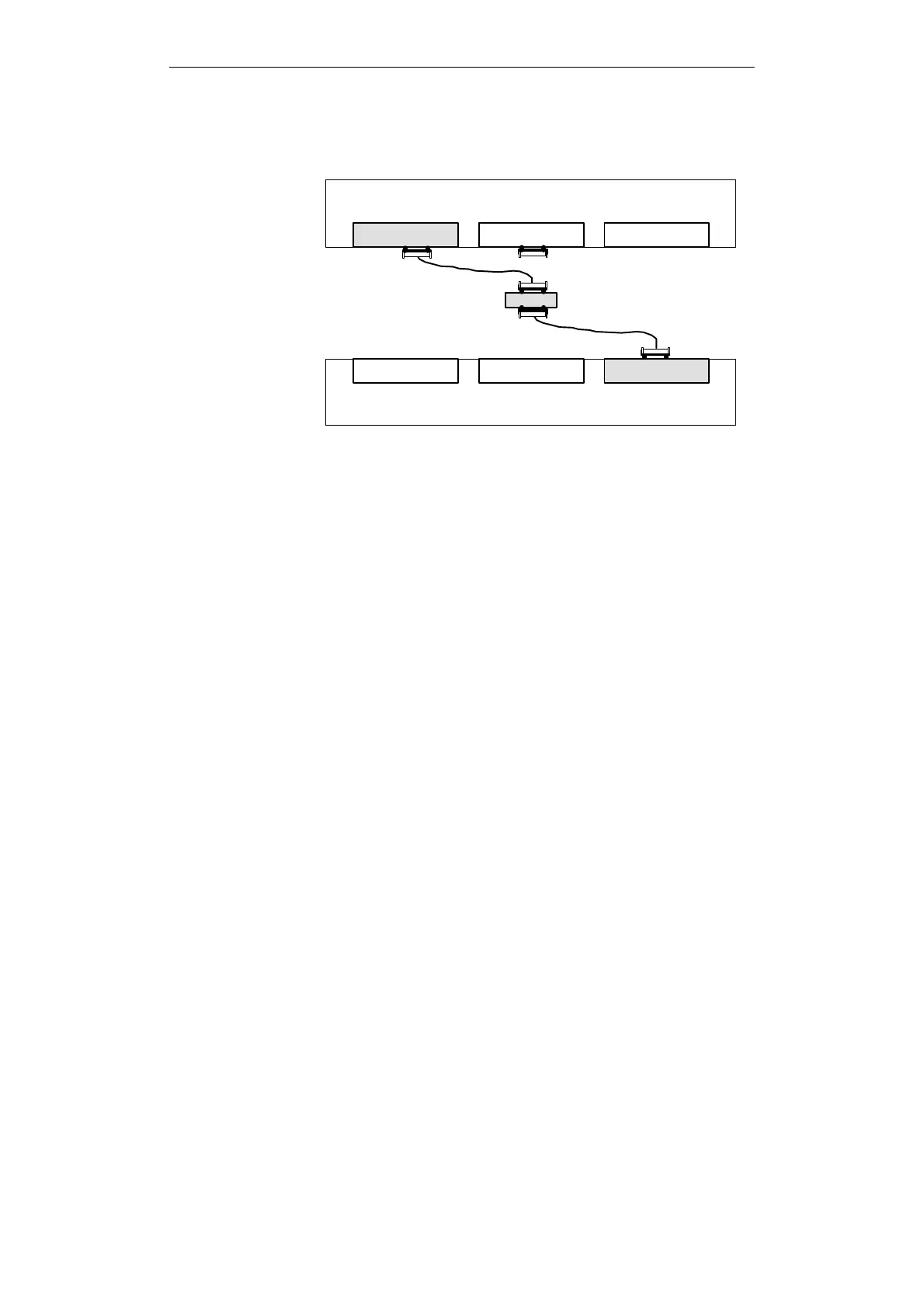
The cable (5) connects the V.24 interface to the Köster box and
cable (10) connects the box to the active TTY interface. The cables
are not supplied with the PG.
COM 1-4 / V.24
LPT 1
Köster Box
COM 1-4 / V.24
LPT 1
COM 1 / V.24
PLC-S5
(5)
(10)
25-pin
25-pin
PG
(PG/PC)
..
..
..
..
..
COM 1 / TTY, active
The PGs are switched off.
The V.24/TTY converter (Köster box) is configured as described in
Chapter 8 V.24/TTY Converter (Köster box):
1. Connect the cable (5) between the COM 1 (V.24) port and the
port of the Köster box.
2. Plug the connector of cable (10) into the 25-pin socket of the
Köster box.
3. Establish the connection to the TTY interface of the partner
PG.
4. Secure the connectors (screw or clip).
Cable (5), Order no. Köster 224 22x
2)
Cable (10), Order no. 6ES5 733-2xxx0
1)
1) xxx is the length key. Refer to the Programmers catalog ST 59.
2) x stands for the connector type of the cable PG - Köster box
(see Chapter 8).
Connecting PGs
with V.24 and TTY
Interface
Procedure
Cables for the V.24
Interface
File Transfer

 Loading...


