4
4-9
Working with S5-DOS/ST
C79000-G8576-C760-03
The PG and the prommer are both switched off.
1. Parallel prommer:
using the supplied LPT cable, connect the
“LPT 1” port on the PG with the “PC” port on the external
prommer and, if applicable, connect your parallel printer to the
“Printer” port of the external prommer.
Serial prommer:
plug the connector labelled “V.24” on the
connecting cable into the COM port of the PC. Plug the 25-pin
connector labelled “PROMMER” into the socket on the rear
side of the prommer.
The connecting cable (1) connects the PG with the prommer
(25-pin).
2. Any connectors fitted with screws or clips must be secured.
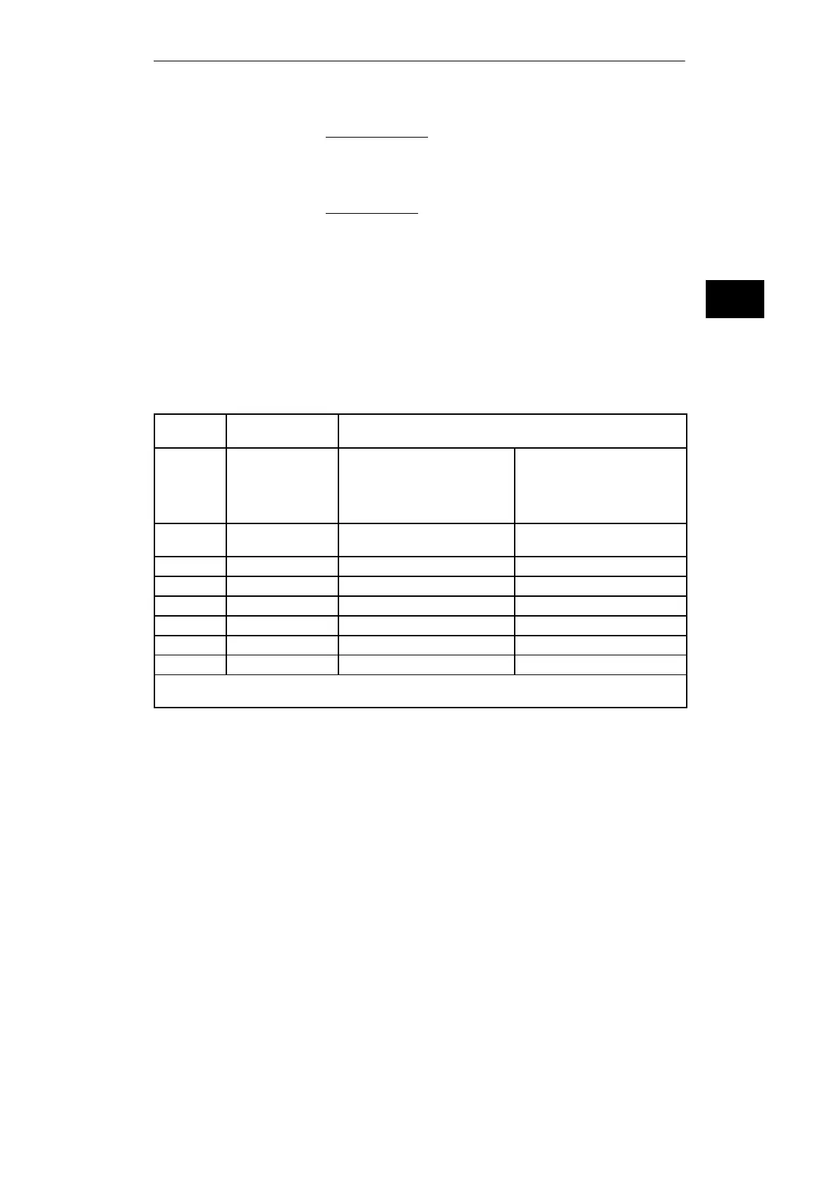
4.4 Overview – Connecting Cables to PLC, Partner PG,
Prommer
Connecting
cable no.
Order number Connection
from (Connector on PG) to
1
6ES5 733-4xxx0
1)
6ES5 733-5xxx0
1)
6ES5 733-6xxx0
1)
6ES5 733-7xxx0
1)
PC COM 2
25-pin male
25-pin female
9-pin male
9-pin female
PROMMER
3 6ES5 731-6AG00 PC COM 1 (PG 7xx:
25-pin male)
Connecting cable 7 or 8 (PLC)
Connecting cable 10 (Partner-PG)
4 6ES5 734-2xxx0
1)
PC COM 1, 2 25-pin female PLC 15-pin female
5 Köster 224 22x PC COM 1, 2 Köster box
6 6ES5 734-1BD20 PC COM 1, 2 25-pin female PLC 15-pin female
7 6ES5 731-0xxx0
1)
Connecting cable 3 or Köster box PLC 25-pin male
8 6ES5 731-1xxx0
1)
Connecting cable 3 or Köster box PLC 15-pin female
10 6ES5 733-2xxx0
1)
Connecting cable 3 or Köster box Partner-PG COM 1
1)
xxx is the length key. The cables are available in lengths ranging from 1m to 1000 m. Please refer to the Programmers catalog ST 59 for details on the
length key. A maximum cable length of 3 m is permitted for use with a prommer.
Connecting your
PG to the Prommer
Installing Hardware

 Loading...


